CAVITY COUNT
How Many Cavities Should the Mold Have? Single, Multi-Cavity and Family Molds
The cavity count is set by the machine, the tolerance and the annual volume, in that order. The tool that gives the lowest cost per part is often not the one with the most cavities.
Three numbers decide the cavity count, and only one of them is commercial: the shot capacity of the press, the clamp force the projected area demands, and the number of parts the tool will realistically produce before it is worn or the design changes. Cavity count is not a measure of how good a tool is. A four-cavity mold that holds tolerance on every cavity is worth more than a sixteen-cavity mold whose middle cavities drift, because the second tool ships scrap faster. This guide sets out the arithmetic, the layouts, and the cases where adding cavities makes a job worse.
What the cavity count actually changes
Every extra cavity adds steel, a gate, a cooling circuit and a set of wear surfaces, and it divides the cycle time across more parts. The trade moves in different directions on different rows, which is why the decision cannot be made on part cost alone.
| What changes | More cavities | Why |
|---|---|---|
| Tooling effort | Higher, close to linear | Extra cavity blocks, gates, water lines and ejector work per position |
| Cycle time | Almost unchanged | Cooling time is set by wall thickness, not by how many parts share the shot |
| Cost per part | Falls, then flattens | Fixed tooling is spread over more parts; once spread, only cycle time matters |
| Machine size | Rises with projected area | Clamp force scales with total projected area, including the runner |
| Dimensional spread | Wider, unless the tool is flow-balanced | Cavity-to-cavity pressure and temperature differences reproduce as size differences |
| Maintenance interval | Shorter per calendar time | The tool makes the same number of parts in fewer press hours |
The shot capacity check
The shot is the plastic needed to fill every cavity plus the runner system, in one injection. It has to sit inside the barrel’s usable shot weight, and the usual guidance is to keep the shot between roughly 20 and 80 per cent of the barrel capacity: below that the melt residence time becomes long enough to degrade heat-sensitive grades, above it there is no cushion left for the hold phase. The check is done on the material actually being moulded, since the same barrel holds very different weights of polypropylene, polycarbonate and glass-filled nylon. A shot that is comfortable in PP can be at the top of the range in a glass-filled grade.
The clamp force check
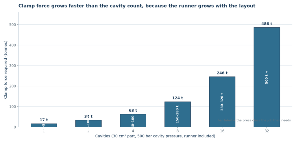
Clamp force holds the tool closed against the pressure inside the cavity. A working figure for the estimate is that one bar of cavity pressure acting on one square centimetre produces one kilogram of separating force, so the force per cavity is the projected area times the cavity pressure (the method is set out in our clamp force and tonnage guide). Use the projected area seen from the opening direction, add the runner, and add a margin for the pressure spike at the gate end of fill rather than the average pressure. The table below is the same part at four cavity counts, with a projected area of 30 cm² per part and a cavity pressure of 500 bar.
| Cavities | Projected area incl. runner | Clamp needed | Press class that fits |
|---|---|---|---|
| 1 | 30 cm² + 4 cm² | 17 t | Small toggle machine, 50–80 t |
| 4 | 120 cm² + 6 cm² | 63 t | 80–100 t |
| 8 | 240 cm² + 8 cm² | 124 t | 150–180 t |
| 16 | 480 cm² + 12 cm² | 246 t | 280–320 t |
Two consequences follow. First, the cavity count is limited by the press that will run the job, not only by the tool budget; a sixteen-cavity tool that needs a 300-tonne press is a poor decision if the plant runs 150-tonne machines and the schedule is already full. Second, clamp force grows faster than the number of parts, because the runner grows with the layout. That is the point where a hot runner starts to pay for itself: removing the runner removes both its projected area and its share of the shot.
Balanced, geometrically balanced and family layouts
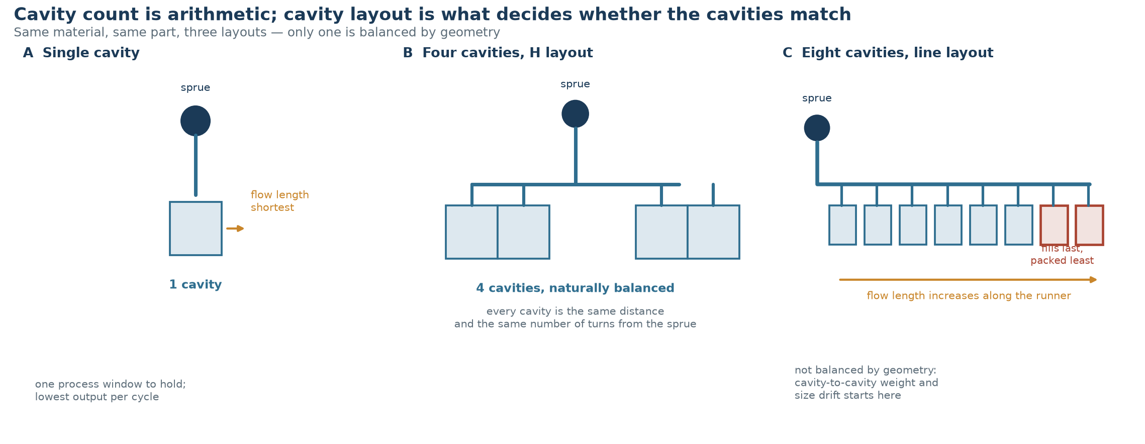
Cavity count and cavity layout are separate decisions. A tool can have eight cavities and still fill them badly. What matters is that every cavity sees the same pressure and the same melt temperature at the same moment, because a cavity that fills late packs less, and a cavity that fills late is a cavity that shrinks more.
- A naturally balanced runner splits the flow symetrically at every branch, so all cavities are the same distance and the same number of turns from the sprue. This is the only layout that is balanced by geometry alone, and it is the reason four- and eight-cavity tools are built on H patterns rather than in a line.
- A geometrically balanced runner accepts unequal branch lengths and compensates with runner diameters. It works, but the window is narrower and it is sensitive to viscosity changes between lots.
- A family mold fills different parts in one shot. It is efficient only when the parts share a material, a colour and a wall thickness, and when their projected areas are close enough that one cavity does not overpack while another starves. A hot runner with individually controlled valve gates turns a family mold from a compromise into a workable tool.
- A line layout with eight or more cavities off a single runner is the classic source of cavity-to-cavity variation, and it is usually visible in the trial report before it is visible in a complaint.
What more cavities do to the tolerance spread
A single-cavity tool has one process window to hold. A sixteen-cavity tool has sixteen, and they are not identical: core and cavity blocks sit at slightly different temperatures, water circuits see different flow rates, and gates are not perfectly identical after polishing. The result is a spread of dimensions that is present from the first shot and stays for the life of the tool. On a part with a tight tolerance, that spread consumes the allowance before production starts.
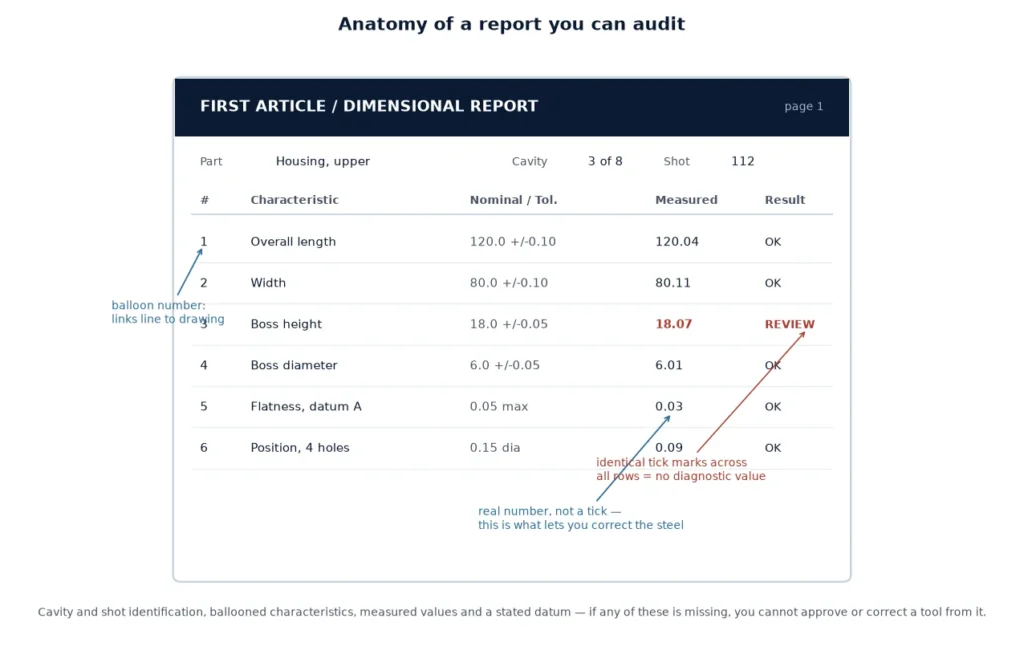
Three habits keep the spread inside the tolerance. Identify the cavities, either by engraving the number on the part or by recording the cavity against the shot in the trial report, so that a drift can be traced to one position instead of the whole tool. Run the dimensional report by cavity rather than on a pooled sample. And set the process window on the worst cavity, not the average one, because the customer’s gauge does not know what the average is.
Steel, wear and the maintenance interval
Cavity count also sets how hard the tool works. Eight cavities means eight times the parts per press hour, so the same annual volume arrives in one eighth of the machine time and the wear surfaces see it just as fast. Ejector pins, slides, gate drops and the parting line all wear per cycle, not per calendar month. On a tool with side action or a hot runner, the cleaning and inspection interval should be set from the shot count (see our maintenance interval guide), and the spare-parts list should hold the same number of wear items as there are positions.
When fewer cavities is the better answer
- Thick walls. When cooling dominates the cycle, extra cavities buy much less than they do on a thin-wall part, because the shot does not get shorter.
- Tight tolerances on several dimensions. The spread across cavities, not the tool, becomes the limiting factor.
- Low volume. A four-cavity tool run for a short campaign never repays its extra steel.
- A design that is still moving. One cavity is cheap to change; four are not, and a change in one position usually has to be repeated in all of them.
- A part that is large relative to the press. The clamp force check decides before the volume argument is even reached.
- Prototype and bridge quantities, where the tool has to exist quickly and the parts have to be real.
Checklist before you fix the cavity count
The following is the sequence we run before the cavity count goes onto a quotation (it sits next to the DFM review), because changing it after the steel is cut is a rebuild rather than an edit.
- Shot weight per cavity plus runner, against the usable barrel capacity of the press that will run the job.
- Total projected area including the runner, times the cavity pressure, with a margin for the pressure peak — then compare with the clamp available.
- Annual volume, divided by the parts the tool is expected to produce between services.
- Tolerance stack on the critical dimensions, and whether the spread across cavities stays inside it.
- Whether the layout can be naturally balanced at that cavity count, and if not, whether a hot runner is justified.
- Cooling, ejection and slide space per position — cavitation is limited by the space the mechanisms need as much as by the clamp.
- Cavity identification and a per-cavity dimensional report at trial.
- The change rule: what happens to the tool, and to the other cavities, if one feature of the part changes after approval.
What this means in practice
Most parts land on one, two, four or eight cavities, and the reason is arithmetic rather than convention: those counts can be laid out symmetrically, they fit the common press sizes, and they keep the tolerance spread manageable. When a job genuinely needs more, the decision is usually driven by a single dominant factor such as a very high annual volume or a very short cycle, and it comes with a hot runner, a per-cavity temperature control scheme and a disciplined trial report. The question to ask is not how many cavities the tool can have, but how many it can fill identically — and that number is what the quotation should be based on.
Frequently asked questions
Does a higher cavity count always reduce the cost per part?
No. It reduces the tooling share of the cost, but it raises the machine size and it can widen the dimensional spread until scrap or sorting eats the saving. On a thick-walled part, or a low-volume part, the extra cavities never repay themselves.
What is a balanced runner?
A runner layout in which every cavity is at the same flow distance and the same number of branches from the sprue, so the melt arrives at all cavities with the same pressure and temperature. Only a symmetric layout — the H pattern used on four and eight cavity tools — is balanced by geometry alone.
How is clamp force calculated for a multi-cavity mold?
Project the part along the opening direction, multiply that area by the cavity pressure to get the separating force per cavity, add the runner area, and add a margin for the pressure peak at the end of fill. The total is the clamp the press has to hold, and it is usually quoted with the press size rather than the part size.
Can one mold run different parts at the same time?
Yes — that is a family mold — but only when the parts share a material, a colour and a wall thickness, and their projected areas are close enough that no cavity overpacks while another starves. A hot runner with individually controlled valve gates makes the arrangement far more forgiving.
How much variation should I expect between cavities?
Expect some, from the first shot. Temperature differences between blocks, uneven water flow and gate polishing differences all reproduce as small dimensional differences. The practical answer is to measure by cavity at trial, set the process window on the worst position, and keep the cavity identified on the part.
Is a hot runner required above a certain number of cavities?
Not required, but the case gets stronger as the count rises. The runner adds projected area, shot weight and scrap, and on a high cavity count those add up in every cycle. Above eight cavities the runner is usually the larger of the two costs to control.
Deciding the cavity count for a new tool?
Send the part drawing, the annual volume and the press you intend to run it on. We will come back with the cavity count the arithmetic supports, the layout that keeps it balanced, and the points on the drawing that would have to change to make a higher count worth building.