Machine selection
Clamping Force and Tonnage: How to Calculate What a Mold Actually Needs
Clamp force is arithmetic, not instinct: projected area times cavity pressure, with a safety factor and a check on everything else the machine has to do. Here is the calculation, the material numbers behind it, and the four places the answer usually goes wrong.
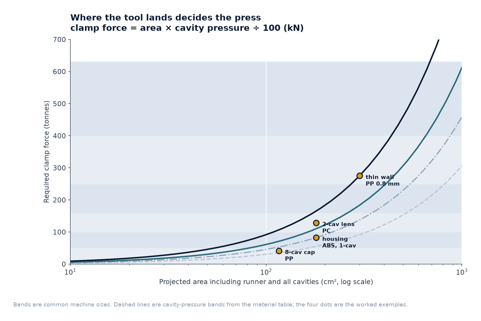
Clamping force in kilonewtons equals the projected area of the cavities and runner in square centimetres, multiplied by the cavity pressure in bar, divided by 100. A single-cavity cover with 200 cm² of projected area running at 500 bar therefore needs about 1,000 kN of clamp — roughly 100 tonnes — before the safety factor. The handbook clamp factors of 2–5 tons per square inch are the same sum with the units already collapsed: 2 t/in² is about 300 bar, 5 t/in² about 750 bar. The arithmetic is easy. What decides whether a tool runs well is which cavity pressure went into it, whether the runner area was counted, and whether the machine can also plasticise, inject and eject what the mold needs.
What actually pushes the two halves apart
Melt pressure acts on every surface of the part, but only the area projected onto the parting plane produces a force that tries to open the mold. That is why the calculation starts from a silhouette, not from the surface area of the part: a ribbed box and a plain box of the same footprint need nearly the same clamp force.
The pressure in that projection is not the injection pressure shown on the machine. It is the cavity pressure, which is almost always lower and which moves through the cycle. It peaks near the gate during filling, then holds through packing. Sizing on nozzle pressure typically over-buys clamp force by a factor of two or three; sizing on a single average number without checking where the gate sits under-buys it on long, thin parts. Use a simulation result, a measured cavity pressure from a similar part, or a conservative material band.
| Resin family | Typical cavity pressure | Equivalent clamp factor | What moves it |
|---|---|---|---|
| PP, PE, HDPE | 250–400 bar | 2–3 t/in² | Long thin flow paths; low viscosity but fast pressure decay |
| ABS, HIPS, SAN | 300–500 bar | 2.5–4 t/in² | Cosmetic surfaces demand higher pack pressure |
| POM, PBT, PET | 400–700 bar | 3–5 t/in² | Crystalline; fast setting needs short, hard packing |
| PA6, PA66 (unfilled) | 500–800 bar | 4–5.5 t/in² | Low viscosity, flashes easily — clamp margin matters |
| PA with 30 % glass | 700–1,000 bar | 5.5–7 t/in² | High viscosity, wear, and gate freeze control |
| PC, PC/ABS | 500–800 bar | 4–5.5 t/in² | High melt temperature, thick sections, long hold |
| Thin wall under 1 mm | 800–1,200 bar | 6–8 t/in² | Fill is pressure-limited; clamp becomes the binding constraint |
Treat the bands as a starting point a simulation or a measured value should replace: the gap between the 400 and 600 bar bands is a whole machine size.
The calculation, in the order that avoids mistakes
- Projected area: measure the silhouette of one part in the parting plane, add the runner’s projection (typically 10–25 % of a small part, much less on a large one), then multiply by the cavity count.
- Cavity pressure: take it from a simulation, from a sensor on a comparable tool, or from the table above on the high side of the band.
- Multiply and convert: kN = area in cm² × pressure in bar ÷ 100; tonnes = kN ÷ 9.81.
- Safety factor: 1.1–1.2 for a uniform-wall part with a central gate; 1.3 for thin walls, long flow paths, family tools or a cold runner with a large sprue. Never below 1.1.
- Check the vertical: slides and lifters are locked by wedges and heel blocks in the closed tool, so side thrust does not add to the clamp figure — but a slide that leans on a weak wedge shows up as local flash at the side core, which is a tool-design problem, not a tonnage problem.
Round the result up to the next standard machine size, then run the checks below before committing.
Four worked examples
| Part | Projected area | Cavities | Resin | Cavity pressure | Required clamp | Machine size |
|---|---|---|---|---|---|---|
| Appliance housing, 120 g | 180 cm² | 1 | ABS | 450 bar | 810 kN ≈ 83 t | 100–130 t |
| Bottle cap, 3 g | 12 cm² + runner → 116 cm² total | 8 | PP | 350 bar | 406 kN ≈ 41 t | 60 t |
| Thin-wall container, 0.8 mm wall | 300 cm² | 1 | PP | 900 bar | 2,700 kN ≈ 275 t | 350 t |
| Lens, 2 cavities | 90 cm² each → 180 cm² total | 2 | PC | 700 bar | 1,260 kN ≈ 128 t | 160–180 t |
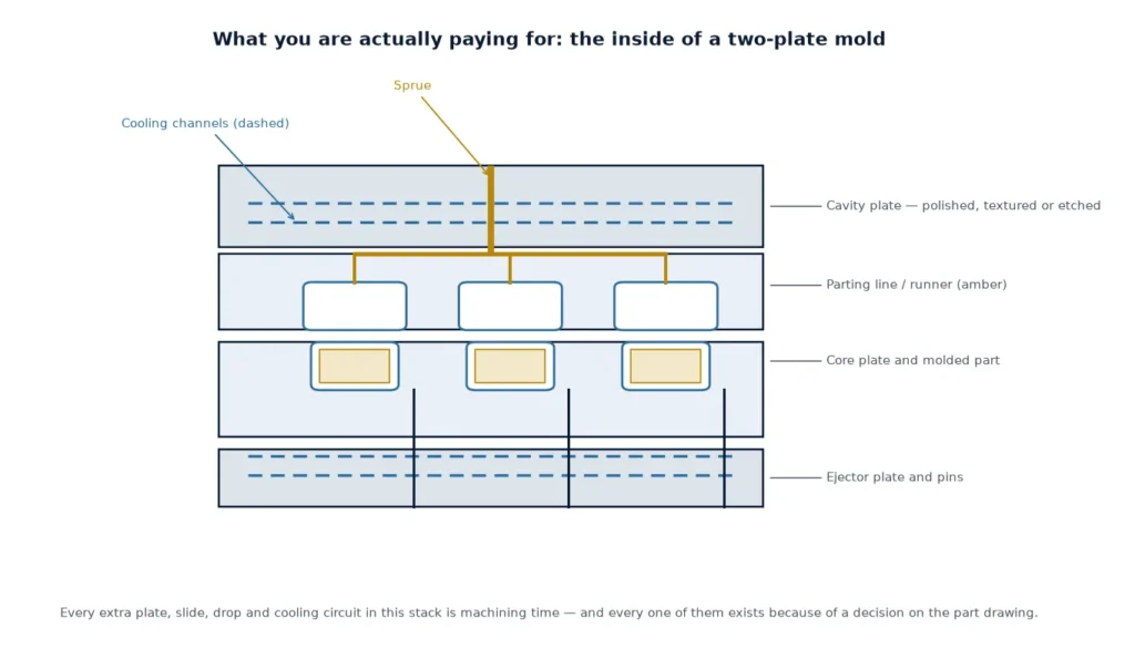
Note the direction each example moves. The cap tool is a small machine with a high cavity count; the container is one cavity and a large machine, because thin walls raise both the area and the pressure. Cavity count multiplies area, so eight small cavities can add up to the same clamp demand as one large one — which is exactly why the eight-cavity tool needs a careful runner balance to make the pressure distribution match the calculation. Tool architecture is covered in the guide to mold types.
Too little clamp looks like a moulding problem
The first symptom is flash at the parting line, usually near the gate or the thickest section. The dangerous part is what happens next: the operator sees a short shot or a void, raises injection pressure or hold pressure, the cavity pressure rises, the separating force rises with it, and the flash gets worse. That spiral ends with the tool being blamed for a tonnage shortfall. A quick check is to drop the clamp force in steps on a running job: if flash appears well below the nameplate rating, the calculation, the tool support or the machine is wrong, and the cause is not the process window.
Mold breathing is the subtler version: the halves separate by a few hundredths of a millimetre, the part comes out thicker in the middle of the face than at the edges, and dimensional reports drift with no visible defect. The tell is a part that measures consistently heavier on a tool otherwise in specification. Flash sits alongside the other three classic defects in warpage, sink, short shot and flash.
Too much clamp costs money quietly
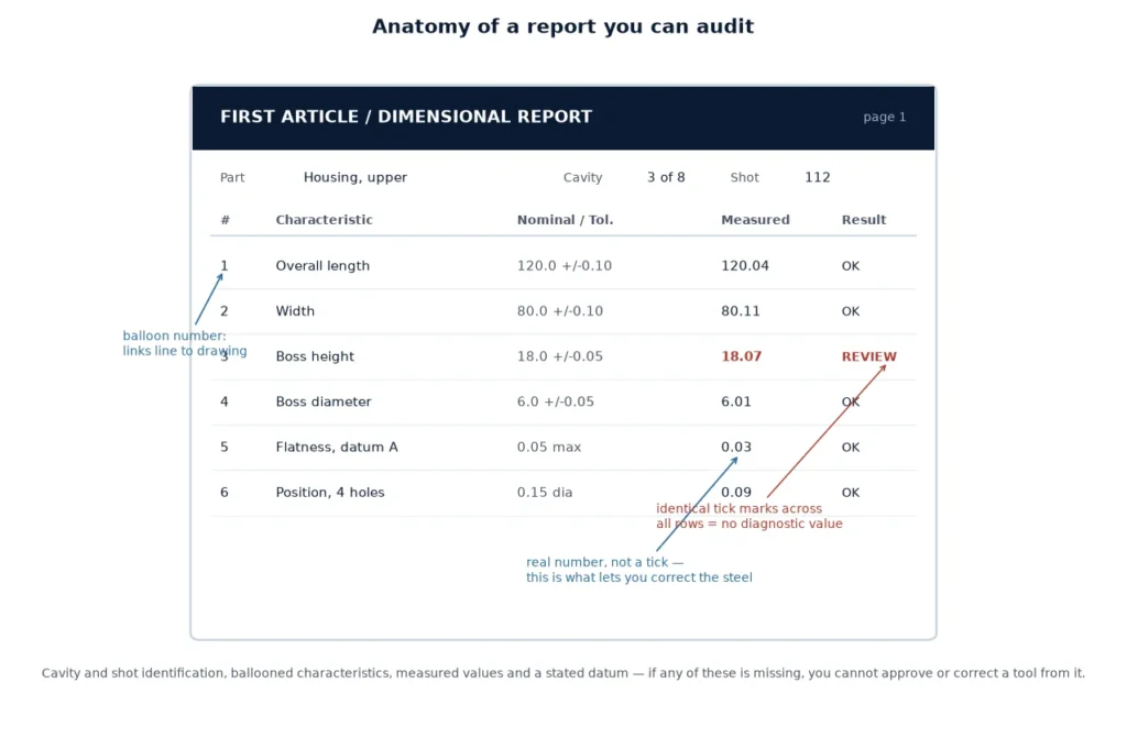
Excess tonnage rarely produces a visible defect, which is why it survives. It crushes vents: a 0.02 mm vent depth is a specification, and a platen that deflects under 30 % more force than the tool needs will flatten it over a few thousand cycles, after which the tool burns and needs re-venting. It peens the parting line, so the tool seals less well and eventually flashes at the very tonnage that used to be enough. It stretches tie bars and loads the toggle or the hydraulic cylinder, and on older machines it shows up as a pressure spike at the moment of clamp-up. None of these appear on the first day’s inspection report.
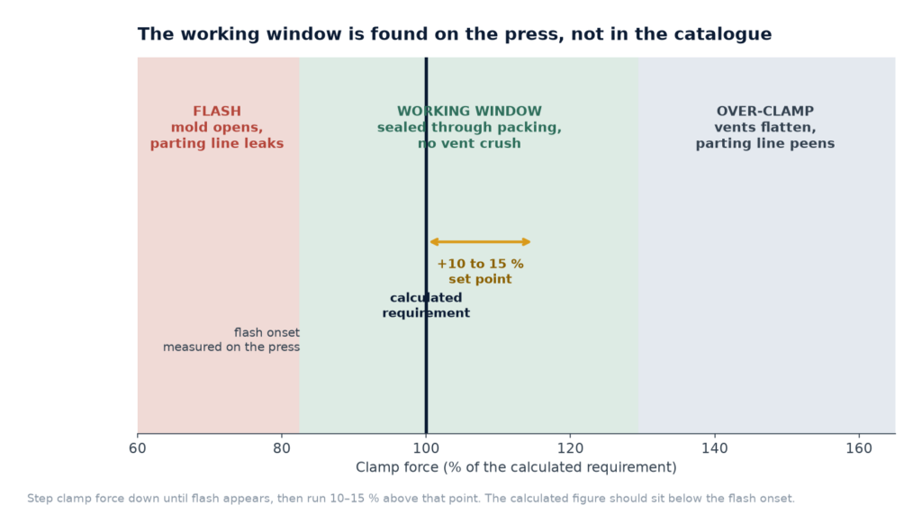
The practical target is the lowest clamp force that seals through packing with a 10–15 % margin — a number you can find on the press in twenty minutes.
The other four things the machine has to do
- Shot size: the part plus runner should sit between roughly 20 % and 80 % of the barrel capacity, so that residence time stays short enough for the resin.
- Plasticising rate: recovery has to finish inside the cooling time, otherwise the cycle is limited by the screw, not the tool.
- Mold space: tie-bar distance, minimum and maximum mold height, daylight and ejection stroke all have to clear the stack — a tool that fits the tonnage and not the platen is still unusable.
- Platen and support: a mould whose footprint is small relative to the platens will deflect in the middle no matter what the clamp gauge says. Support pillars under the cavity block are cheaper than a bigger machine.
These four are why a quote cannot be checked on tonnage alone. Matching a project to an existing press means the whole set has to clear before the design is frozen. The process side is in plastic injection molding services, and the tool side in mold design and engineering.
Where the number goes wrong
- The runner was left out of the area, which on a small multi-cavity tool can be a 20 % shortfall on its own.
- One cavity of a multi-cavity tool is overpacked, so the real force is set by the worst cavity, not the average the calculation used.
- The resin changed after the machine was chosen — ABS to glass-filled PA can raise cavity pressure by half again at the same wall.
- A family tool with parts of different sizes was sized on the average area instead of the largest local demand.
- The tool has been re-cut or re-polished, and the parting line no longer has the contact area it was designed with, so the same tonnage now produces less sealing.
A two-shot tool deserves a separate note: the second shot sees a different projected area and a different resin, so the clamp demand is set by whichever shot is worse, and the rotating or shuttle half adds its own stiffness question. The constraints are set out in two-shot and overmolding design constraints.
Confirming the figure on the press
Whatever the calculation says, the truth is measurable. Step the clamp force down in 10 % increments while the process is stable and watch for the first sign of flash, then set the production value 10–15 % above that point. On a machine with a hydraulic clamp gauge, check that the gauge reading corresponds to real force — multiply the hydraulic pressure by the clamp cylinder area, or measure tie-bar strain — because a gauge on a twenty-year-old press is a display, not a measurement. Record the number on the tool card so the next run starts from it instead of re-learning it.
Checklist before booking a machine
- Projected area includes runner and all cavities, measured from the parting plane silhouette.
- Cavity pressure has a source: simulation, sensor or a conservative material band.
- Safety factor chosen from part type, not from habit.
- Shot weight between 20 % and 80 % of barrel capacity.
- Tie-bar distance, mold height, daylight and ejection stroke all clear the stack.
- Mold footprint supported across the platens, with support pillars if the area is small.
- Clamp force confirmed on the press and written on the tool card.
Frequently asked questions
Is clamping force the same as tonnage?
In everyday use, yes: “tonnage” is clamp force expressed in metric tonnes, where 1 tonne is about 9.81 kN. The rating on the machine nameplate is the maximum clamp it can apply, not the force a particular mold should run at, which is usually 10–30 % lower.
Should I use injection pressure or cavity pressure for the calculation?
Cavity pressure. Injection pressure is measured at the nozzle or the hydraulic system and includes the whole pressure drop through the sprue, runner and gate, so it can be two or three times the pressure the part actually sees. Sizing on it is the fastest way to book a machine one size too large.
My part flashes even though the clamp force is well above the calculation. Why?
Usually uneven support or worn contact. If the cavity block is not supported in the middle, the plate deflects and the halves separate locally at the tonnage the calculation predicted for the whole face. Worn parting surfaces, a damaged vent land or a bent ejector plate produce the same symptom. Measure the plate deflection or add support pillars before adding tonnage.
Does a hot runner reduce the required clamp force?
Slightly, because the cold sprue projection is gone and the manifold sits behind the stationary platen. In practice the saving is small on anything but a tiny part, while hot-runner tools usually run at higher pack pressure, which offsets it. Do not size a machine on the assumption that the hot runner halves the runner area.
How do I find the real clamp force on an older machine?
From the clamp cylinder: hydraulic pressure times effective piston area, including the toggle’s mechanical advantage. Tie-bar strain measurement is the more direct alternative. Nameplate ratings assume an unworn machine; worn seals and stretched tie bars mean the true maximum is lower.
Checking a tool against the press before the steel is cut
Send the part model, the resin grade and the machine specification — clamp rating, tie-bar distance, shot capacity and platen size — and we will confirm whether the tool fits, and which of the two is the constraint.