COOLING
Mold Cooling Circuit Design: Layout, Turbulence and ΔT
Cooling decides the cycle before any other tool feature does. These are the four numbers that set it, and how to check a circuit drawing against them.
Design the cooling circuit around turbulent flow and a small temperature rise. In practice that means 8–12 mm channels, water velocity of 1.5–2.5 m/s (Reynolds above 4,000), no more than 2–5 °C rise across any single circuit, drilled paths about 1–1.5 channel diameters below the cavity surface and pitched roughly three diameters apart. Get those numbers right and cooling stops being the constraint; miss them and no amount of chiller capacity will recover the cycle, because the bottleneck is the heat transfer at the channel wall, not the temperature of the water leaving the plant.
Cooling is most of the cycle, so it is where seconds live
In a typical oil-free engineering resin part, cooling accounts for roughly half to two-thirds of the cycle. Filling is fast, packing is bounded by the gate freeze, and ejection and handling are fixed by the machine and the robot. That leaves cooling as the only phase with real room to move — which is why circuit design deserves more attention than the choice of chiller brand.
| Phase | Share of cycle (indicative) | What actually controls it |
|---|---|---|
| Injection / fill | 5–10 % | Fill rate, gate size, viscosity, wall thickness |
| Packing / holding | 15–25 % | Gate freeze time, part weight, shrinkage target |
| Cooling | 50–65 % | Wall thickness, mold steel conductivity, coolant flow and ΔT |
| Ejection, robot, handling | 5–15 % | Tool design, robot path, part drop |
Cooling time scales with the square of wall thickness, so a 10 % thicker wall costs about 20 % more cooling time before anything else changes. That single relationship explains most of the difference between two quotes for the same part: one tool is designed around the nominal wall, the other has a rib or a boss that quietly doubles the local section. Section control is a part-design decision that the cooling circuit can only partly compensate for.
Flow rate, not water temperature, is what people get wrong
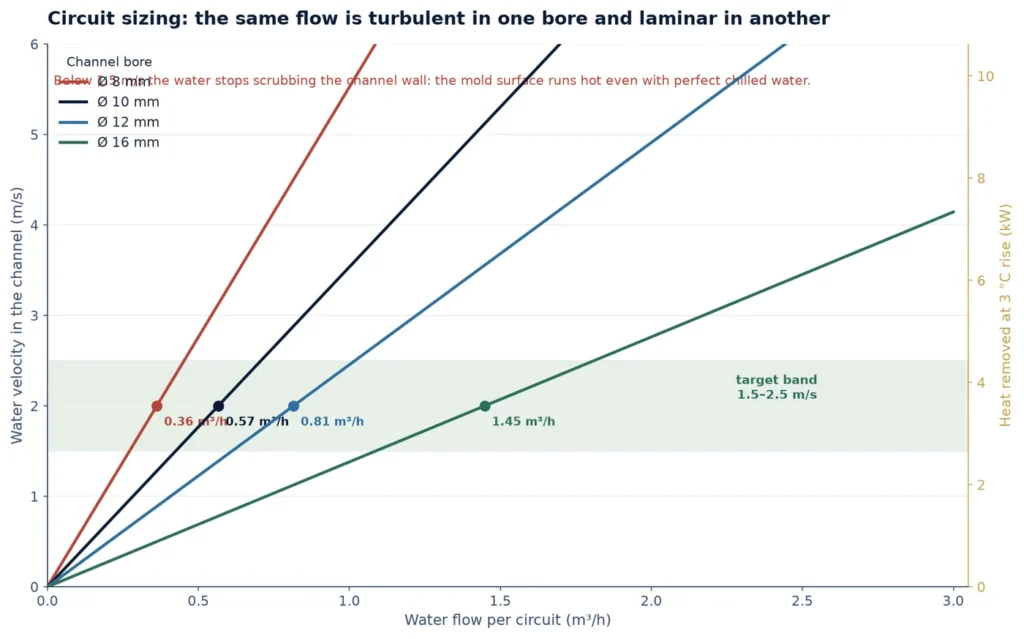
A circuit fed with 14 °C water at half the flow it needs will run hotter than the same circuit fed with 18 °C water at the right flow. Heat transfer at the channel wall depends on the convection coefficient, and that coefficient collapses once the flow leaves the turbulent regime. Below roughly 1.5 m/s in a 10 mm channel, water that was carrying heat away in a turbulent stream becomes a laminar core sliding past a stagnant film at the wall, and the mold surface temperature climbs even though the chiller is working perfectly.
The practical test is a return-flow measurement per circuit, not a temperature gauge on the manifold. A rotameter on each return line and a pair of thermometers across the circuit tell you both the flow and the temperature rise; from those two numbers you can calculate the heat the circuit is actually removing and compare it with the heat the part has to lose.
Channel size and flow: one table to size a circuit
Every circuit has to satisfy two constraints at once: enough velocity to stay turbulent, and enough total flow to carry the heat away within the allowed temperature rise. The two constraints meet in a narrow band, which is why circuit diameter and circuit count are a matched pair rather than independent choices.
| Channel bore | Flow for 2 m/s | Heat removed at 3 °C rise | Typical use |
|---|---|---|---|
| 8 mm | 0.36 m³/h | ≈ 1.3 kW | Small cores, sliders, baffles, hot spots |
| 10 mm | 0.57 m³/h | ≈ 2.0 kW | General cavity and core circuits |
| 12 mm | 0.81 m³/h | ≈ 2.8 kW | Large plates, high-shot tools |
| 16 mm | 1.45 m³/h | ≈ 5.1 kW | Manifolds, main supply loops, big cores |
As a worked example, take a 500 g polypropylene part on a 20 s cycle. Losing about 425 kJ/kg between melt and ejection at 0.025 kg/s of throughput is roughly 10–11 kW of heat to remove, continuously. At a 3 °C rise that needs about 3 m³/h of water — which is five 10 mm circuits, or three 12 mm circuits, not one 16 mm line split four ways at the plate. The arithmetic is simple and worth doing before the plate is drilled, because it decides how many circuits the tool needs.
Series or parallel: pick the failure mode you can live with
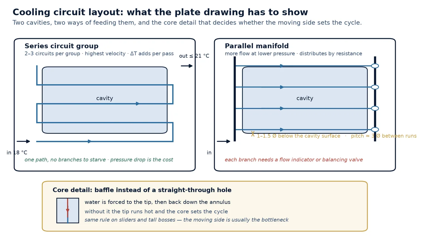
A series circuit — one continuous path through the plate — gives you higher velocity and a predictable temperature rise per pass, at the cost of pump pressure. A parallel arrangement fed from a manifold gives more total flow at lower pressure, but it distributes by resistance, so the branch with the shortest path or the cleanest channel takes the most water and the others starve. In practice the good compromise is short series groups of two to four circuits, fed from a manifold with a balancing valve or a flow indicator on each group.
- Keep each circuit under roughly 1.5 m of drilled path; long serpentines lose temperature control and the far end runs cold and slow
- Feed the core before the cavity where possible — the core is usually the harder side to cool and the one that sets the cycle
- Use baffles or bubblers in tall cores: a drilled hole with a straight tube down the middle will short-circuit at the tip and leave the top of the core hot
- Put the inlet at the heaviest section and the outlet at the thinnest, so the coldest water meets the most heat
- Avoid running cooling lines through the parting line or within one diameter of ejector holes, water fittings and dowel bores
- Allow for scale: a 1 mm deposit on a 10 mm channel is a 20 % loss of flow area, which is a laminar circuit within a year
Distance from the cavity surface is a compromise, not a rule of thumb
Channels too far from the surface leave a thick layer of steel between the heat and the water; channels too close risk distortion of the cavity surface, cracking under clamping force, and a short tool life. The workable band is one to one and a half channel diameters from the surface — about 10–15 mm for a 10 mm channel — with a pitch of roughly three diameters between parallel runs. Where the part geometry forces a thin wall behind the cavity, the answer is usually a smaller channel on a tighter pitch rather than one large channel further back.
Steel choice moves the same needle. P20 conducts heat at roughly 29 W/m·K, H13 at about 25, aluminium around 170 and copper alloys in the 105–160 range. That is why a copper insert behind a hot spot can shorten a cycle where adding another circuit cannot — and why the steel selection decision should be taken together with the cooling layout rather than before it.
Temperature difference targets by part type
A single ΔT figure across the whole tool is usually a sign that nobody has thought about which surfaces matter. Tighten the target where dimensional control and appearance are critical, and accept a wider band where the part is forgiving — the cost of tightening is more circuits, more manifolds and more flow.
| Part type | Circuit ΔT target | Mold surface uniformity | Why |
|---|---|---|---|
| General industrial parts | 5–8 °C | ±5 °C | Cycle time dominates; small warpage is tolerated |
| Engineering / technical parts | 3–5 °C | ±3 °C | Shrinkage and flatness are specified |
| Precision, optical, thin-wall | 1–2 °C | ±1 °C | Birefringence and micron-level flatness |
| Crystalline resins (PP, POM, PA) | 3–5 °C | ±3 °C | Sharp crystallization window; uneven cooling shows as warpage |
| Amorphous resins (ABS, PC, PS) | 5–8 °C | ±5 °C | Wider processing window, more tolerant of ΔT |
A circuit drawing you can check in five minutes
Most cooling problems are visible on the drawing before any steel is cut. Take the plate drawing and mark each circuit end to end: if you cannot trace continuous flow from inlet to outlet without guessing, the tool will have a dead zone there.
- Count the circuits and the flow you can supply: each 10 mm circuit needs about 0.6 m³/h to stay turbulent
- Check the temperature rise per circuit against the target in the table above
- Look for the core and slider cooling, not just the cavity plate — most cycle losses hide on the moving side
- Confirm every circuit has its own inlet and outlet at the manifold, with a flow indicator or a balancing valve
- Check the distance from the cavity surface and the pitch between runs against the one-to-three diameter rule
- Confirm fittings, hoses and quick couplings are not smaller than the circuit they serve — a 6 mm hose on a 10 mm circuit costs most of the flow
Once the tool is running, cooling maintenance is what keeps the design honest: scale, rust and hose debris all reduce flow long before anything fails visibly. The return temperatures drift first, which is why a maintenance schedule written around measured signals beats one written around months.
Where conformal cooling earns its place — and where it does not
Conformal cooling, whether by laser-sintered inserts or by milled conformal channels, removes the geometric compromise of straight drilling: the channel can follow the part surface at constant depth. On a deep core, a hot-spot near a boss, or a part with a long thin section, that can take double-digit percentages off the cooling time. On a simple flat plate it usually changes nothing, because the drilled layout was already close to the ideal path. The honest test is whether the drawing shows a place where the straight hole cannot reach — if it does not, the money is better spent on more circuits and better flow.
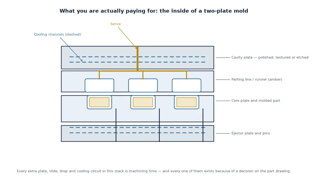
Cooling also interacts with the other tool decisions in ways that are easy to miss: it sets where the ejector pins and the water fittings can go, and it constrains the parting line. Bringing the circuit layout into the mold design and engineering review is cheaper than discovering the conflict at the drilling stage, and it is one of the differences that shows up in the cost structure of a tool rather than in its price.
Frequently asked questions
Does colder water always shorten the cycle?
No. Below a certain temperature the limit is the heat transfer coefficient at the channel wall, not the water temperature, so dropping the supply from 18 °C to 12 °C buys very little while raising the risk of condensation on the mold faces and on the part. Most tools run best with supply water around 15–20 °C and enough flow to keep the circuit turbulent. Fix the flow before touching the chiller setpoint.
How do I know whether my flow is turbulent?
Measure the return flow per circuit and calculate the velocity from the channel bore. For water in the 15–25 °C range, 1.5 m/s in a 10 mm channel is comfortably turbulent (Reynolds well above 4,000); below about 1 m/s the same channel is transitional and the mold surface will run hot at the far end. A rotameter on each return line costs little and turns the question from an argument into a reading.
Should circuits be in series or parallel?
Series gives higher velocity and a predictable temperature rise, at the cost of pump pressure; parallel gives more flow at lower pressure but distributes by resistance, so some branches can starve. Short series groups of two to four circuits fed from a manifold with balancing valves is the arrangement that behaves well in practice, particularly on tools with several similar plates.
Why does cycle time creep up over the life of the tool?
Almost always because flow falls while the water temperature stays the same: scale in the channels, rust from a steel manifold, or hose debris at a quick coupling. A 1 mm deposit in a 10 mm channel removes about 20 % of the flow area, which can drop the circuit out of the turbulent band entirely. Watching return flow and ΔT per circuit catches it months before the operator notices the cycle.
How many circuits does a plate need?
Divide the heat load by the capacity of one circuit at your allowed temperature rise. A 10 mm circuit removes roughly 2 kW at a 3 °C rise, so a part that needs 10 kW of cooling needs about five such circuits — regardless of how many the plate happens to have room for. Adding circuits without adding flow simply splits the same water into slower streams.
Want the cooling layout reviewed before the plate is drilled?
Send the part drawing, the resin and the target cycle. We will check the circuit count, the channel layout and the flow needed against the heat the part has to lose, and flag the places where the geometry forces a compromise.