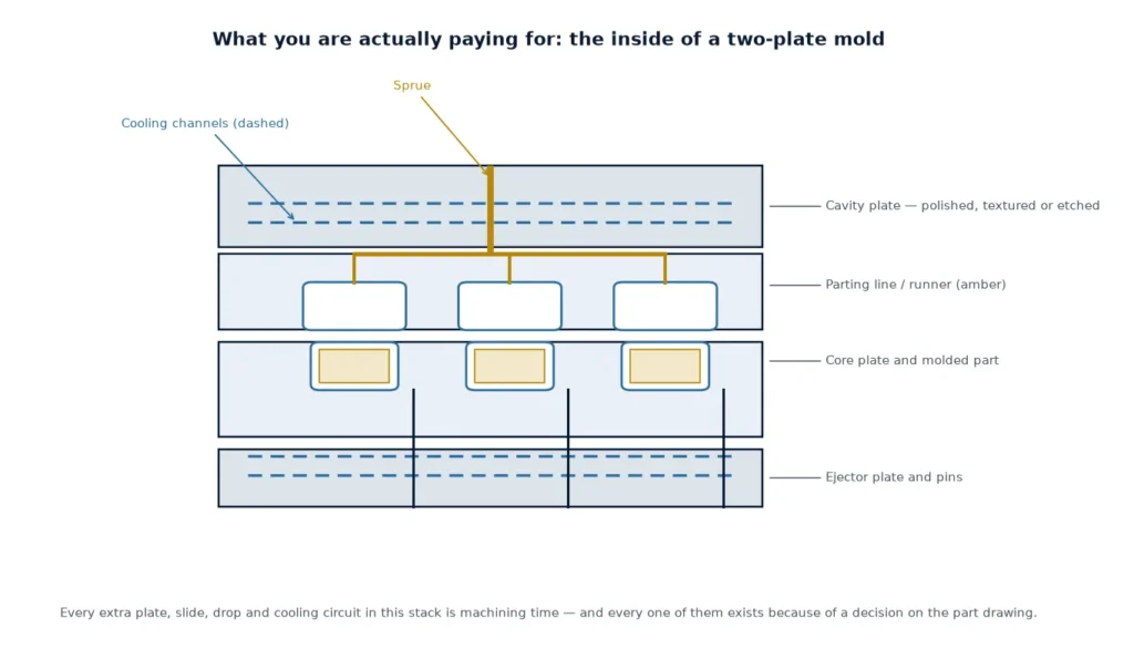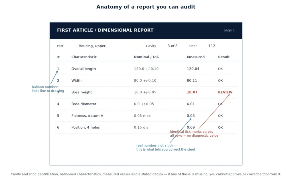
MAINTENANCE
Mold Maintenance Schedule: What to Check, How Often, and What It Prevents
A schedule built on the calendar misses the point. Wear follows shot count, resin and water quality — here are four tiers you can put on the shop floor, with pass criteria for each.
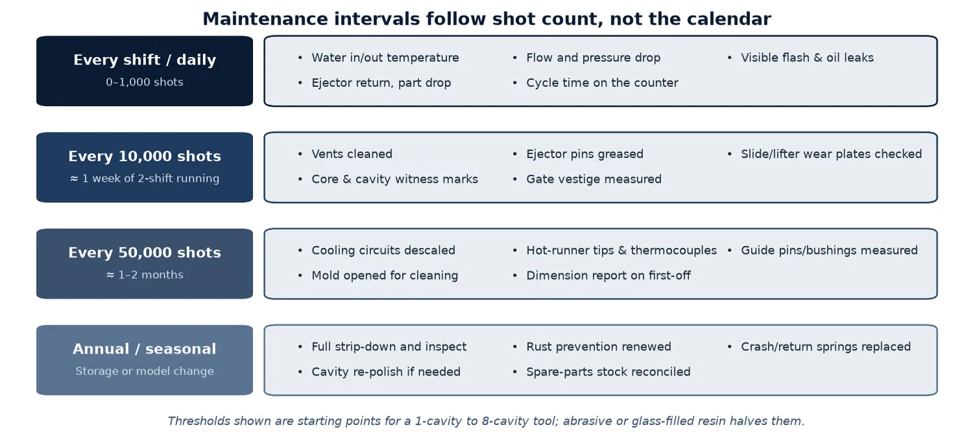
Build the schedule from shot count, not from dates. Four tiers cover almost every injection tool: every shift, every 10,000 shots, every 50,000 shots, and an annual or pre-storage service. Each tier needs a written check, a pass criterion and a named owner. Anything that fails its criterion becomes a work order on the tool, not a note in a log book.
The reason to tie maintenance to cycles rather than weeks is that wear is caused by three things that have nothing to do with the calendar: how many times the tool has closed, what resin ran through it, and what the cooling water carried in. A tool that runs 200,000 shots in a quarter needs more attention than one that ran 4,000 shots over a year in storage.
Why the calendar is the wrong clock
Two tools built to the same drawing age at completely different rates. Glass-filled polyamide at 300 °C melt temperature wears a gate and a shut-off several times faster than unfilled PP at 220 °C. Hard water scales a cooling circuit until the mould runs hot at the corners while the controller reads normal. A tool that sits idle in a humid store corrodes faster than one in daily use with oil on it.
So the schedule has to be written per tool, with the interval adjusted for resin abrasiveness, water hardness and the cosmetic standard of the part. The tiers below are the starting structure; the numbers inside them move with the application.
Tier 1 — every shift
Tier 1 is a two-minute visual and numerical check done by the moulder, not the toolroom. It exists to catch the failures that happen inside a single shift: a blocked water line, a broken return spring, a part sticking in the cavity.
- Water in and out temperature on every circuit; a difference above 3–5 °C between in and out needs a flow check.
- Flow or pressure drop across the manifold, recorded, not just observed.
- Flash at the parting line and at every shut-off, checked on the first ten parts.
- Oil or grease on the leader pins and on the slide ways, no dry metal visible.
- Ejector plate returns fully; limit switches or return springs intact.
- Part drops freely; no part left in the cavity at cycle end.
- Cycle time against the counter — a creeping cycle is the earliest signal of a cooling problem.
Tier 2 — every 10,000 shots
Tier 2 is the first tier that normally needs the tool stopped, or at least opened at the bench. For a two-shift operation it lands roughly weekly; for a single-cavity tool in a low-volume programme it may be monthly. What matters is that the counter triggers it, not that Friday triggers it.
- Clean the vents — cavity, runner and any insert interface. Do not enlarge them; measure depth if they look polished out.
- Grease ejector pins, leader pins, slide ways and lifter pads with the specified high-temperature grease.
- Inspect slides, lifters and cams for wear steps, scoring and loosened wear plates.
- Look for witness marks on cores, cavity inserts and any shut-off band.
- Measure the gate vestige on a sample and compare with the first-off value.
- Check hot-runner tip condition and thermocouple response on a heat-up ramp.
- Wipe the parting line and record any flash bead that forms at the same place twice.
Tier 3 — every 50,000 shots
Tier 3 is a planned stop with the tool on the bench, and it is where most of the value of a maintenance programme sits. Wear that is still measurable here is cheap to correct; the same wear found at 150,000 shots usually means welding, re-machining or a new insert.
| Check | Method | Pass criterion |
|---|---|---|
| Guide pin and bushing clearance | Micrometer on pin, bore gauge on bushing | Clearance within 0.02 mm of the drawing value |
| Ejector pin length and tip form | Height gauge against the plate datum | All pins within 0.05 mm of each other |
| Shut-off land step | Straight edge and feeler, or blue check | No step that can be felt; no blue transfer across the land |
| Cooling circuit flow | Flow meter at the inlet, per circuit | Within 10% of the recorded baseline |
| Core and cavity polish | Visual under 10× magnification | No corrosion pits, no gate wash, no crack lines at corners |
| Part dimensions | First-off dimensional report on a sample | Inside 50% of each tolerance band |
| Hot-runner heater and thermocouple | Resistance and response check | Heater within specification; thermocouple reads ambient correctly |
Tier 4 — annual, seasonal or before storage
This tier exists for tools that change programme, go into storage or run seasonally. It is also the right moment to review whether the tier intervals still match reality: a tool that failed twice at 10,000 shots wants 7,500, not a reminder to try harder.
- Strip the tool down; inspect all seals, springs and wear plates; replace consumables rather than re-fitting them.
- Renew rust prevention on every machined surface, including cores, slides and ejector plates.
- Reconcile the spare-parts stock and reorder what was consumed during the year.
- Re-polish or re-texture any surface that has drifted from the approved finish.
- Update the tool file with the shot count, the repairs done and the next planned service point.
Cooling water decides mold life more than most people expect
Scale is an insulator. A tenth of a millimetre of deposit on the inside of a cooling channel measurably reduces heat transfer, and the first symptom is not a hot mould — it is a longer cycle, then warping at the corners of the part, then a dimension that drifts out of tolerance late in the run. By the time the moulder complains about the part, the tool has been running hot for weeks.
Practical measures: record flow per circuit at commissioning and treat a 10% loss as a descaled circuit, keep the water in the turbulent range rather than laminar, and check the ΔT across the tool rather than the set temperature on the controller. Where a tool stands unused for weeks, blow the circuits dry before storage; standing water plus air is how cores pit.
Hot runner maintenance is its own schedule
A hot half adds components that fail without warning: heater bands, thermocouples, tips, valve-gate pistons and seals. The maintenance logic is different too — most hot-runner faults announce themselves as a temperature deviation or a pressure shift before they produce a bad part, so the readings matter as much as the visual checks.
- Record heat-up curves per zone; a zone that lags its neighbours is on its way out.
- Check tip wear and gate freeze behaviour every 50,000 shots, or sooner for glass-filled resin.
- Inspect valve-gate piston seals and air lines; a slow pin shows up as a gate vestige change.
- Pressure-test the manifold after any heater replacement, before the tool goes back in the press.
- Keep one spare of each heater, thermocouple and tip type on the shelf; these are the parts that stop a press.
When maintenance turns into repair
A schedule is only useful if it produces decisions. Three rules we apply when the measurements come back marginal: a fault that appears three times at the same location is a design or wear problem and gets repaired properly; a dimension that has drifted past half the tolerance band is reworked before the next run; and a shut-off that needs polishing every service gets a hardened insert instead of a fourth polish.
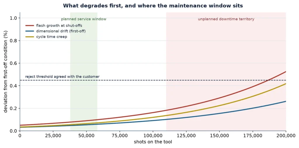
The three curves above are the reason the tiers are built around counters. Flash grows at the shut-offs, dimensions drift as the cavity wears at the gate, and cycle time creeps as the circuits scale. All three accelerate after roughly 60,000 shots on a glass-filled job, and all three are visible on parts before they are visible in a report — which is what the defect signature list is for.
What the maintenance log must contain
A log that records “cleaned and greased” tells you nothing six months later. The record has to be numeric, so a trend exists at all.
| Field | Why it is recorded |
|---|---|
| Date and shot count at service | Places the service on the wear curve |
| Resin and colour run since last service | Explains sudden changes in wear rate |
| Every measurement taken, with the criterion | Shows drift before failure |
| Water flow and ΔT per circuit | Turns cooling into a trend instead of a guess |
| Parts replaced, with batch or serial | Traces a repeat failure to a part number |
| Name of the person who signed off | Makes the schedule real |
| Next service point in shots | Triggers the next stop from the counter |
Spare parts worth keeping on the shelf
Downtime is usually caused by a low-value part. The list below is what we recommend a customer holds for a tool in regular production, scaled to cavitation and to how critical the part is.
| Item | Typical holding | Note |
|---|---|---|
| Ejector pins, standard sizes | 2–4 of each size in the tool | Most common unplanned stop |
| Return and spring washers | One full set | Fatigue, not wear, retires them |
| Water seals and O-rings | Two sets | Age in storage; rotate stock |
| Hot-runner heater and thermocouple | One of each type | Zone-specific, cannot be substituted |
| Hot-runner tips | One per gate type | Wear fastest with filled resin |
| Guide pin and bushing pair | One pair | Only if the tool is above 500,000 cycles |
| Core/cavity insert | Case by case | Decided by cavitation and part criticality |
Storage and restart
A tool in storage is not resting; it is corroding. Before a tool leaves the press for more than a few weeks: clean every surface, dry the cooling circuits with air, apply a film of rust preventive to cores, cavities, slides and ejector plates, close the tool on a soft spacer rather than metal to metal, and record the shot count and the last service in the tool file.
On restart, do not run production immediately. Bring the tool to temperature, cycle a few parts on a soft resin or with reduced pressure, check that every circuit flows, and inspect the first-off part against the last dimensional report from the previous run. That comparison is the fastest way to find what changed in storage.
Where this connects to the rest of the tool
Maintenance cannot compensate for a tool that was built with the wrong clearances or the wrong steel. If a shut-off or a gate keeps coming back, the answer is usually in the original design: steel grade and heat treatment are covered in mold steel selection, the tolerance stack and the ejection concept in mold design and engineering, and the first-off evidence that a tool is actually healthy in reading a T1 trial report. Our equipment and quality control page lists the measuring equipment behind those numbers.
Frequently asked questions
How often should an injection mold be serviced?
Tie it to shot count: a visual and numerical check every shift, a bench service every 10,000 shots, a planned stop with measurements every 50,000 shots, and a full strip-down annually or before storage. Halve the intervals for glass-filled or abrasive resin.
Is cleaning the vents really that important?
Yes. A vent that has flashed over stops the air leaving the cavity, and the moulder answers with more injection pressure. That pressure goes into the shut-offs and the ejector system, so a vent problem becomes a flash and wear problem within a few thousand shots.
What cooling water quality should a mold see?
Clean, filtered, in the turbulent range, with hardness controlled and a recorded flow per circuit. Scale is an insulator; a thin deposit costs cycle time long before it shows as a hot mould.
How do I know when a mold needs repair rather than maintenance?
Three signals: the same fault returning at the same location three times, a dimension that has drifted past half its tolerance, or a shut-off that needs polishing at every service. Each of those is a repair decision, not a cleaning decision.
Should the moulder or the toolroom keep the log?
The moulder records tier 1 daily because they see the parts; the toolroom owns tiers 2 to 4 and signs them. One document, two authors, with the shot counter as the common reference.
Do hot-runner tools need a different schedule?
They need extra items rather than a different structure: heat-up curves per zone, tip and thermocouple checks every 50,000 shots, and a manifold pressure test after any heater work. Spares for heaters, thermocouples and tips should be held on site.
Need a maintenance plan for a tool you already run?
Send the tool drawing, the shot count and the resin you run. We will mark the service points and the measurements worth recording for that specific tool.