Design review
DFM Checklist Before Cutting Steel: 12 Checks That Decide How the Mold Runs
Most mold problems are decided on the part drawing, months before anyone cuts steel. These are the twelve checks we run at DFM, who has to answer each one, and what changes when the answer comes back bad.
Why DFM happens before the tool, not after the trial
DFM — design for manufacturability — is often sold as a service you buy to be safe. In practice it is a short list of questions asked at a specific moment: after the part geometry exists and before the mold layout is frozen. Ask them earlier and there is nothing to check yet. Ask them later and the answers cost tool changes instead of a drawing revision.
The reason to do it is arithmetic. A wall thickness change on a drawing costs an hour of CAD time. The same change after the core and cavity are cut means welding, re-machining, re-heat-treatment and a new trial round. A gate that moves after the first trial usually means a new insert. Nothing in DFM is difficult; it is only cheap at one point in the calendar and expensive everywhere else.
What follows is the checklist we actually run, in the order the questions come up. It is written for the buyer as much as for the toolmaker, because half of these items can only be answered by the product side. If you are preparing a quotation package, this is also the list that decides whether two toolmakers are quoting the same job — design and engineering is where those answers get pinned down.
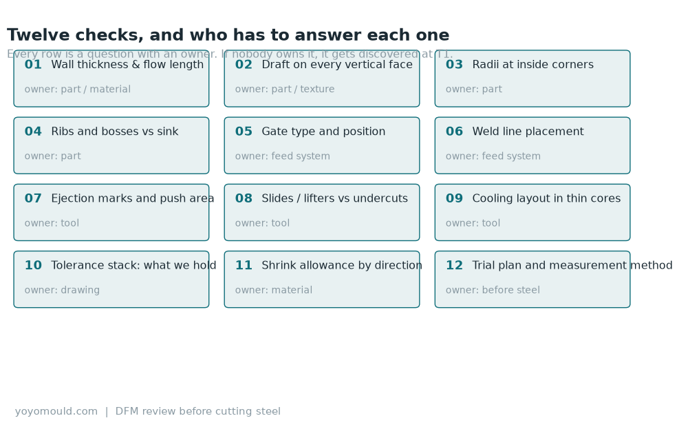
The twelve checks, and who owns each one
Each row below has an owner. When a review stalls, it is almost always because a row has no owner — a wall thickness nobody will change, a tolerance nobody will relax, a weld line nobody has looked at on the cosmetic side of the part.
| Check | What goes wrong if it is skipped | Owner |
|---|---|---|
| Wall thickness and flow length | Short shots, or sink where the wall is thick | Part design + material |
| Draft on every vertical face | Scuffing and drag marks on ejection | Part design |
| Inside radii | Stress concentration, cracking in service, hesitation flow | Part design |
| Ribs and bosses | Sink on the show face, voids in thick bosses | Part design |
| Gate type and position | Weld lines in a visible area, jetting, gate vestige complaints | Feed system |
| Weld line placement | A cosmetic reject that only shows after texturing | Feed system |
| Ejection marks | Dished or marked faces on the non-show side | Tool |
| Undercuts | Slides that add cost and steal cycle, or a part that cannot be ejected | Tool |
| Cooling in thin cores | Long cycle on one feature, differential shrinkage | Tool |
| Tolerance stack | A tool built to hold what the drawing never needed | Drawing |
| Shrink allowance | Out-of-tolerance dimensions at T1 in the flow direction | Material |
| Trial and measurement plan | Arguments about whether the part is good | Before steel |
01 Wall thickness and flow length
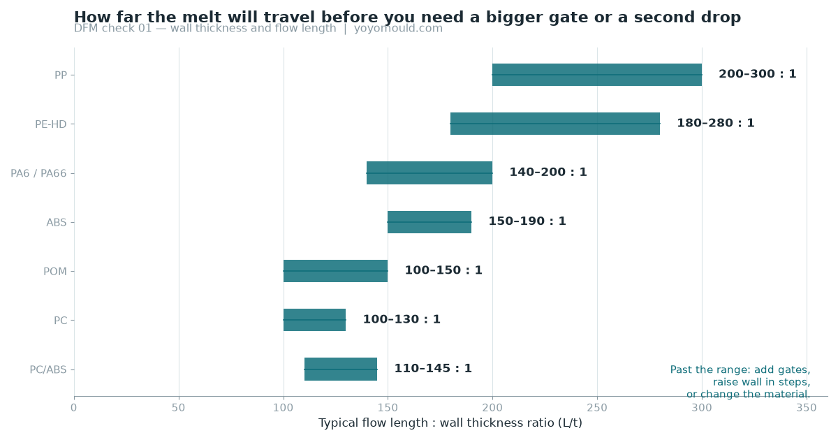
The first question is always how far the melt has to travel from the gate to the last point that fills, measured against the wall thickness. That ratio — flow length divided by wall — is the single number that predicts whether a part fills comfortably, fills only with a high injection pressure, or does not fill at all.
Every material has a practical range. Push past it and the press tells you in the only way it can: short shots at the far end, or flash at the gate while the far end is still empty. The standard fixes are to add a gate, to thicken the wall in steps rather than uniformly, or to change material. What does not work is turning up the pressure and hoping.
02 Draft, and 03 radii
Draft is the cheapest insurance in the tool and the most commonly forgotten on the part drawing. Any face parallel to the direction of opening will drag. On a textured surface the requirement grows with the texture depth, and it applies to the core side too — a deep core with no draft will scuff on the way out even if the cavity side is perfect.
Inside corners want a radius for three reasons: it removes a stress riser in the plastic, it removes a stress riser in the steel, and it lets the melt flow around the corner instead of hesitating there. A sharp internal corner is a crack that has not happened yet, in both the part and the mold.
04 Ribs, bosses and where sink appears
Sink is not a cooling problem. It is a thickness problem that shows up after cooling. A rib drawn as thick as the wall will pull a visible depression on the opposite face; the usual rule is a rib at roughly half to two thirds of the wall, with a generous root radius to keep flow and strength.
Bosses are worse because they are locally thick in both directions. The practical answers are a cored boss, a boss with a thinner wall than the drawing suggests, or a small secondary operation. This is where the injection molding process and the part design have to agree, because no amount of gate tuning will fix a boss that was drawn as a solid cylinder.
05 Gates, 06 weld lines, 07 ejection
The gate decides where the melt enters and therefore where the flow fronts meet. Two flow fronts meeting produce a weld line, and a weld line on a textured or painted surface is a visible line with slightly different gloss and strength. Moving a gate is cheap on a drawing and expensive in steel, which is why we place gates against the cosmetic requirements explicitly rather than by habit.
Ejection follows the same logic on the other side of the part. The push area has to sit where the part can take the force — behind ribs, along a flat land, or on a face that will not be seen. Ejector marks on a visible face are a design decision that was made by nobody, and the defect list in the four common molding defects is essentially this checklist failing in four different ways.
08 Undercuts, 09 cooling, 10 tolerances
Every undercut is a mechanism: a slide, a lifter, an insert. Mechanisms add maintenance, steal cycle time and create a new failure mode. Sometimes there is no alternative, and then the question becomes whether the feature can be redesigned so the mechanism is not needed.
Cooling is where the cycle time actually lives, and thin cores are where cooling is hardest to place — a tall thin core has little room for a water line and heats up in the middle. Baffles, bubblers and high-conductivity inserts are the usual answers, and they need to be decided while the core is still a drawing.
Tolerances deserve a separate conversation because they are routinely over-specified. A dimension marked to a tenth of a millimetre that has never mattered will still be chased in the tool room, and still be argued about at trial. A tolerance stack review asks which dimensions are functional, which are cosmetic, and which are inherited from an older drawing that nobody remembers.
11 Shrink, 12 the trial plan
Shrink is not one number. It differs by material, by direction relative to flow, by wall thickness and by mould temperature. Applying a single isotropic shrink factor is how a part arrives at T1 with one dimension long and another short. Glass-filled materials make this worse, and the gate position is part of the reason.
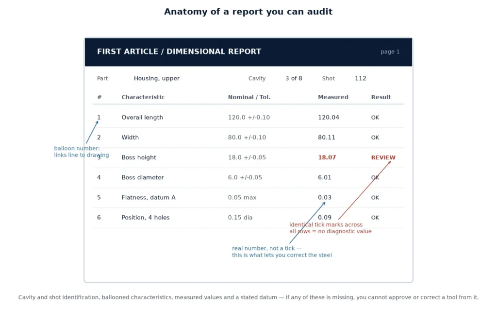
The final check is the one most often left out: how the part will be measured and what counts as a good part. Agreeing the measurement method, the datum scheme and the sample size before steel is cut turns the trial from a negotiation into a pass or fail, which is exactly what the T0 and T1 trial process is for.
What a DFM report contains
A useful report is short and specific: the part, the material, the proposed gate layout, the flow length ratio, a list of changes requested with the reason for each, and a marked-up drawing. It is not a list of generic rules. If a report could have been written before anyone looked at your part, it was not a review.
It also has to distinguish between what must change and what is merely preferable. Toolmakers who mark everything as critical get ignored, and then the one item that mattered gets ignored too. We separate the two lists, and we show the calculation or the comparison behind each item, so the part designer can disagree with a number instead of with an opinion.
When the answer changes the part, not the mold
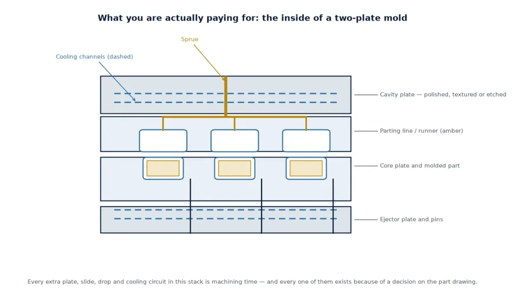
Roughly half of the changes that come out of DFM are part changes, not mold changes: a wall thickened here, a boss cored there, a tolerance relaxed, a texture moved off a weld line. That is normal, and it is the point. A mold is a very expensive way to discover that a drawing was ambiguous. If you want to see how this fits into the wider tooling picture, the mold types and tooling options page lays out the structures this checklist is applied to, from two-plate tools to two-shot designs where the second shot adds its own set of constraints.
Send the part drawing and the material, and tell us which faces are cosmetic. That is enough to run the twelve checks and come back with the two lists. Tell us about the part and we will start from the drawing rather than from a quotation.
Frequently asked questions
When should DFM be done — before or after the quotation?
Both, at different depths. A quotation needs enough of the checklist to know whether the tool is a straightforward two-plate job or something with slides and a hot runner, because that changes the structure. The full review belongs after the order, before the mold layout is frozen, while the part drawing can still change cheaply.
Does a DFM review mean the design gets changed?
Often, yes — and usually on the part, not the mold. Thickening a wall, coring a boss, adding draft and relaxing an unnecessary tolerance are drawing edits. They are also the cheapest edits available, because they happen before any steel is cut. We separate items that must change from items that are merely preferable, so the part side can decide with the reason in front of them.
Can you work from a STEP file without a dimensioned drawing?
For geometry checks, yes: wall thickness, draft, radii, undercuts and flow length can all be read from the solid. For tolerances and the measurement plan we need the dimensioned drawing, because the question is not what the shape is but which dimensions are functional and how they will be inspected.
What if the material has not been chosen yet?
Then it is the first item on the list, not a detail for later. Flow length, shrink, draft requirement and weld line strength all follow from the material. Choosing a resin after the mold layout is fixed is how a tool ends up running at the edge of its process window for its whole life.
How long does a review take?
It depends on the part and on how complete the drawing is, and we would rather give you a date after seeing the file than a number now. What we can say is that the review is a bounded task — it ends with two lists and a marked-up drawing, not an open-ended conversation.
Have a part drawing you want reviewed?
Send the solid model, the material and the cosmetic requirements. We will come back with the twelve checks, the changes we consider necessary, and the ones we only recommend.