UNDERCUTS
Undercuts in Injection Molding: Slider, Lifter, Collapsible Core or a Part Redesign
An undercut is any feature that cannot leave the tool in the opening direction. The option that adds the least steel is almost always the right one, and it is usually a drawing change rather than a mechanism.
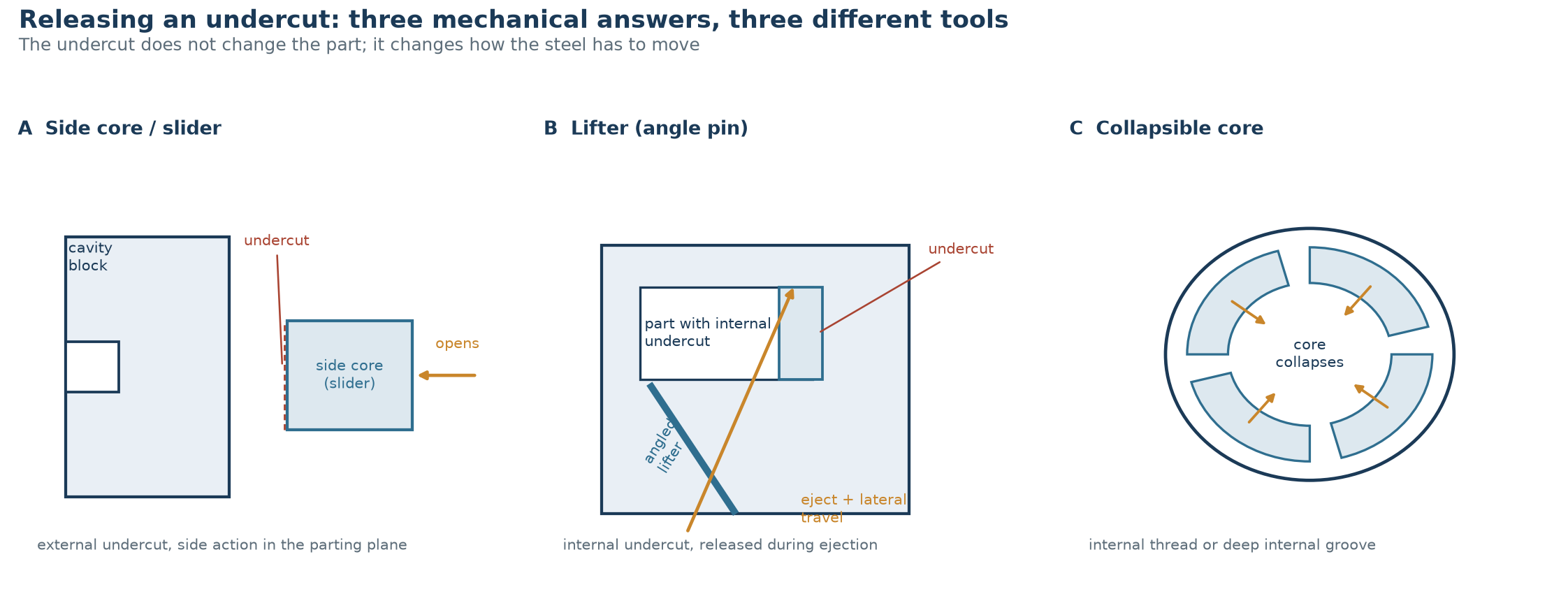
An undercut needs a mechanism only when the part cannot be changed. External undercuts that face sideways are handled by a side core; internal undercuts under the core are handled by a lifter, a collapsible core or an unscrewing unit; and a large share of the undercuts that reach a toolmaker could have been removed at the drawing stage by a bump-off, a slot to the edge, or one small change to a clip geometry. This guide sets out what counts as an undercut, the four ways to release one, what each of them adds to the tool, the cycle and the maintenance routine, and the review we run before quoting a tool with side action.
What actually counts as an undercut
The test is geometric, not visual. Project the part along the opening direction: any surface whose normal points sideways, or which would have to drag across steel as the halves separate, is an undercut. A feature that looks awkward but releases in the draw direction is free; a feature that looks simple but traps steel is not. In practice the same five families account for most of them:
- External windows, clips, grooves and bosses whose opening faces a side wall.
- Internal snap hooks, internal grooves and ribs that sit below the core face.
- Threads of any kind, unless the part is unscrewed or the thread is a jumping thread designed to strip.
- Holes, slots and cross-bores that are not parallel to the opening direction.
- Textured or stepped walls where the draft turns negative part-way down the wall.
Four ways to release an undercut
Each mechanism buys freedom in the part and pays for it in the tool. The comparison below is about construction, not about commercial terms; every option is a design decision that shows up in tool height, cycle time or maintenance.
| Method | Where it works | What it adds to the tool | Effect on the cycle | Wear item |
|---|---|---|---|---|
| Side core / slider | External undercut in or near the parting plane | Slide block, angle pin, wear plates, stop block, its own cooling | Extra opening stroke; the slider is often the last thing to cool | High: guides, wear plates, seals |
| Lifter (angle pin) | Small internal undercut under the core | Angled ejector, guided seat, clearance in the core | Released during ejection, minimal extra time | Medium: lifter face and seat |
| Collapsible core | Internal thread or deep internal groove | Segmented core, wedge, springs, guiding | Collapse and reset each cycle | Medium: segments and wedge faces |
| Unscrewing unit | Precise threads, large diameter | Gear or rack drive, or a servo unit, plus rotation control | Adds rotation time to every cycle | Medium: drive and thread inserts |
| Bump-off (forced ejection) | Shallow undercut in a flexible resin | Nothing beyond a polished, radiused release face | No change, or a slightly slower ejection | Low, but part damage risk |
Sliders: the default answer for external undercuts
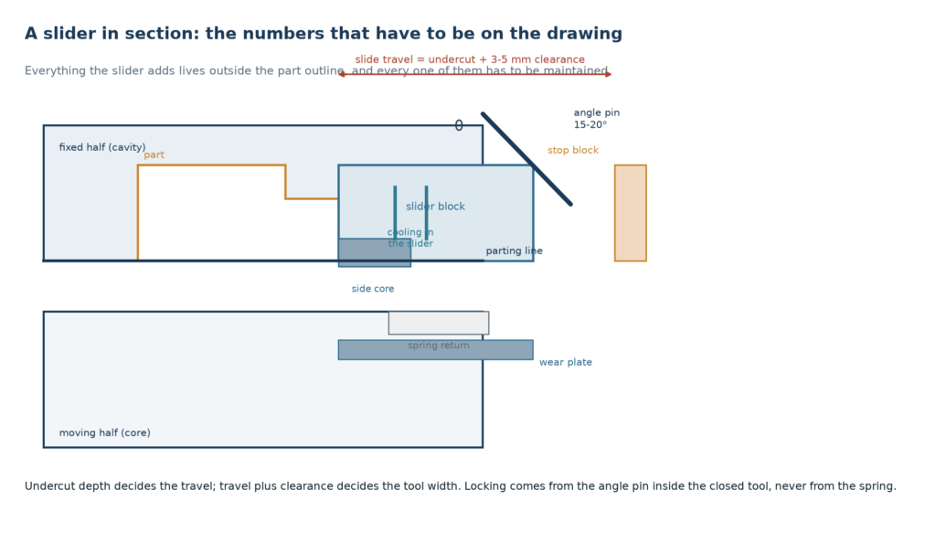
A side core is the workhorse. It travels in the parting plane, driven by an angle pin as the tool opens, and it is locked by that same pin when the tool is closed. Two numbers have to be on the drawing before anything is cut: the slide travel, which is the undercut depth plus three to five millimetres of clearance, and the angle of the pin, normally 15 to 20 degrees. A steeper pin gives more travel per millimetre of opening but loads the pin and the guide harder, which matters on a tool that runs millions of shots.
The cost of a slider is not the block. It is everything the block needs: a hardened guide system, wear plates that can be shimmed, a stop block that survives the return stroke, a spring that brings the slide home before the pin re-enters, and cooling routed into a moving part. It also widens the tool, because the slide has to travel somewhere, and it can force the machine selection if the tie-bar spacing is tight.
One detail is worth insisting on at the design stage: the slider needs its own cooling. A moving block with no water runs hotter than the surrounding cavity, the part cools unevenly against that face, and the area around the undercut becomes the place where warpage and sink marks start. The same reasoning that governs the main circuit applies to the slide, and our guide to cooling circuit design and cycle time covers the layout rules.
Lifters: the internal undercut under the core
A lifter is an ejector pin that leans. As the ejector plate moves forward, the angled pin pushes the part forward and sideways at the same time, which releases a small internal undercut in the same motion that ejects the part. There is no extra mechanism, no extra stroke and no extra cost beyond the guided seat, which is why it is the first thing to consider for internal clips and hooks.
The limits are real. The angle is usually held to 10 to 15 degrees; beyond that the pin binds in its seat and the lateral force starts to distort the part instead of releasing it. The undercut it can release is small, typically in the region of one to two millimetres and resin dependent, and the lifter face has to be shaped so that it pushes on a strong part of the geometry rather than on the thin lip that forms the clip. Ejector stroke has to be long enough to clear the undercut before the part is pushed off, which is a machine specification and not a tool detail.
Collapsible cores and unscrewing units
Threads and deep internal grooves cannot be lifted or stripped. A collapsible core splits into segments that move inward as the core retracts, so the part is released without rotation; an unscrewing unit rotates the core or the part instead, driven by a rack, a gear train or a servo. Both are legitimate and both are expensive in tool construction and in maintenance, so they are chosen when the thread is a functional feature rather than a convenience.
Two practical notes. First, thread start position: if the part has to assemble in a specific orientation, the thread start has to be indexed, and that adds control hardware to the tool. Second, resin stiffness: a collapsible core works because the segments move, so the part must be rigid enough to be pushed off without deforming, which is the opposite of what a bump-off needs.
The figure below is the section we ask for on any tool with a slider: travel, pin angle, locking, wear surfaces and cooling all visible on one drawing, so the mechanism can be reviewed before steel is ordered.
Designing the undercut out
Before a mechanism is quoted, the part is worth a second look. Several changes remove the undercut entirely, and they are all cheaper than the steel they replace:
- Open the feature to the edge. A clip that reaches the parting line, or a slot cut through to the side wall, stops being an undercut and becomes part of the draw.
- Use a bump-off. A shallow undercut can be forced out of a flexible resin if the release face is polished and radiused and the strain stays inside the resin’s limits. Useful starting points are a few percent of the undercut diameter for polypropylene and less for the stiffer amorphous resins; the real limit comes from a trial, not from a table.
- Split the part. Two mouldings that clip together often cost less tool than one moulding with three sliders, and they usually assemble faster.
- Move the split line. Repositioning the parting plane can put an undercut in the opening direction without touching the part’s function.
- Loosen the tolerance that created it. A retention bead often needs less interference than the drawing shows, and a smaller bead may strip safely.
What side action does to the tool and the cycle
Every slider converts a simple two-plate tool into a mechanism with a maintenance schedule. The effects are predictable: tool height and width grow to accommodate travel; the slide is a wear item whose guides and plates need checking on a defined interval; the split between slide and cavity is a potential flash path that has to be fitted and maintained; cooling in a moving block is harder to route and more likely to leak; and the slider face is often the last area to freeze, which sets the cycle.
None of that argues against side action; it argues for counting it. One well placed slider is routine. Four sliders, two lifters and a collapsible core is a tool that will spend its life in maintenance, so trading a mechanism for a drawing change is the highest-value decision in the review.
The review we run before quoting side action
- Confirm the undercut really is an undercut, projected along the opening direction.
- Count the mechanisms, and ask which of them the part can live without.
- Check the undercut depth against the strip limits for the specified resin.
- Set slide travel at undercut plus clearance, and state the pin angle.
- Confirm the machine has the opening stroke, ejector stroke and tie-bar spacing the mechanism needs.
- Route cooling into every moving block, and say where the hoses go.
- Name the wear parts and the interval at which they are checked.
- Agree the cosmetic acceptance around the split line before the steel is polished.
How an undercut changes machine selection
Side action is not only a tool question. A slider adds height to the tool and needs opening stroke to travel; a lifter needs ejector stroke longer than the part depth plus the undercut clearance; and the extra projected area of a slide face adds to the clamping force the machine has to hold, which is the calculation set out in clamping force and tonnage. On an existing machine, these three numbers are often what decides which mechanism is affordable before any tool design starts.
Steel choice follows the same logic. Slider faces and lifter tips run under sliding contact and take the wear, so they are usually specified harder than the cavity, with a surface treatment where galling is likely; the comparison in mold steel selection applies, and the heat-treatment options are covered in nitriding and PVD for mold steel. Where the undercut also changes the fill pattern, the gate discussion in gate types and gate location is the next thing to revisit, because a side core can block the flow path the gate was placed for.
How the choice usually lands
Small internal hooks end up on lifters. External windows and clips end up on sliders, one per face where the geometry allows. Threads end up on collapsible cores below roughly 60 mm and on unscrewing units above that. Flexible resins with shallow undercuts are bumped off, and everything that can be designed out is designed out before a quote is written. The mechanism is the last resort, not the first answer.
Frequently asked questions
Is an undercut always a slider?
No. A slider is only one of four answers and it is the one that adds the most steel. Small internal undercuts usually go on lifters, threads on collapsible cores or unscrewing units, and shallow undercuts in flexible resins are often bumped off. The right question is which mechanism adds the least to the tool, not which mechanism is standard.
How deep can an undercut be before it must be moulded with side action?
Depth matters less than direction and resin. If the feature cannot be stripped within the strain the resin tolerates, it needs a mechanism regardless of how shallow it is. As a starting point, polypropylene strips a few percent of the undercut diameter, commodity amorphous resins noticeably less, and glass-filled grades very little at all.
Does a slider always lengthen the cycle?
Not by itself, but it often does indirectly. The slide needs opening stroke, and the face against the moving block frequently cools last, so the effective cooling time is set by the slider rather than by the main cavity. Cooling routed into the slider is what keeps the penalty small.
Can a lifter release a thread?
No. A lifter moves in one direction during ejection and cannot follow a helix. Threads need either a collapsible core, where the segments retract, or an unscrewing unit that rotates the core or the part.
What angle should the angle pin be?
Fifteen to twenty degrees is the usual range. Shallower pins need more opening stroke for the same travel; steeper pins give more travel but load the pin and guide harder and are riskier on high-volume tools.
Send the drawing with the undercut marked
Tell us the resin, the faces that must stay mark-free and which undercut you would rather avoid. We will come back with the mechanism we would use, the travel and angle we would put on the drawing, and the drawing change that could remove it entirely.