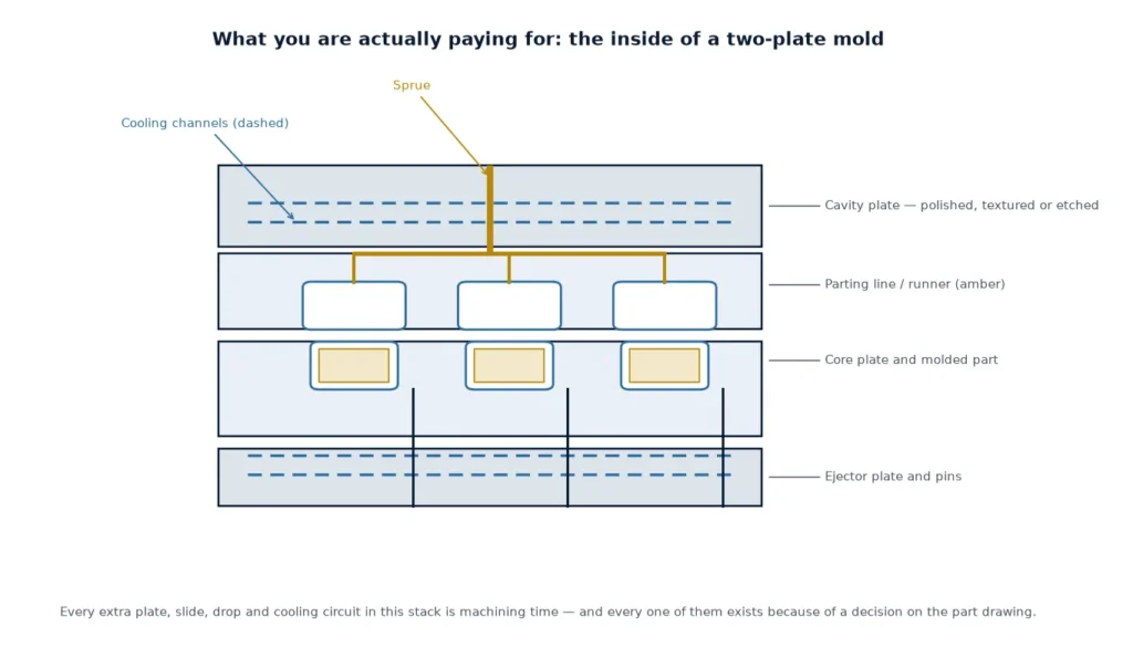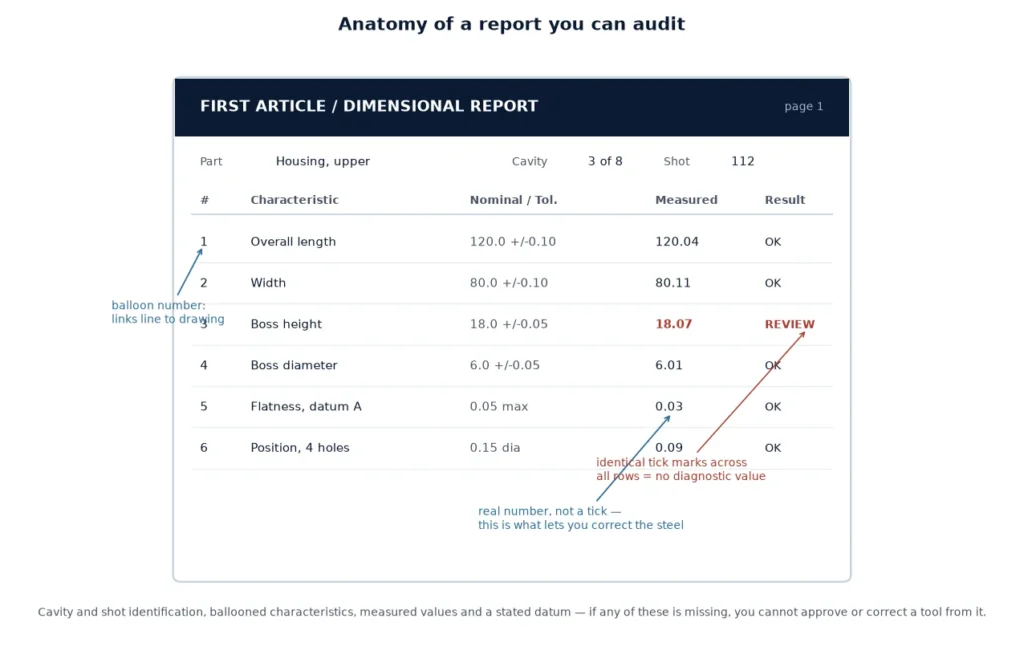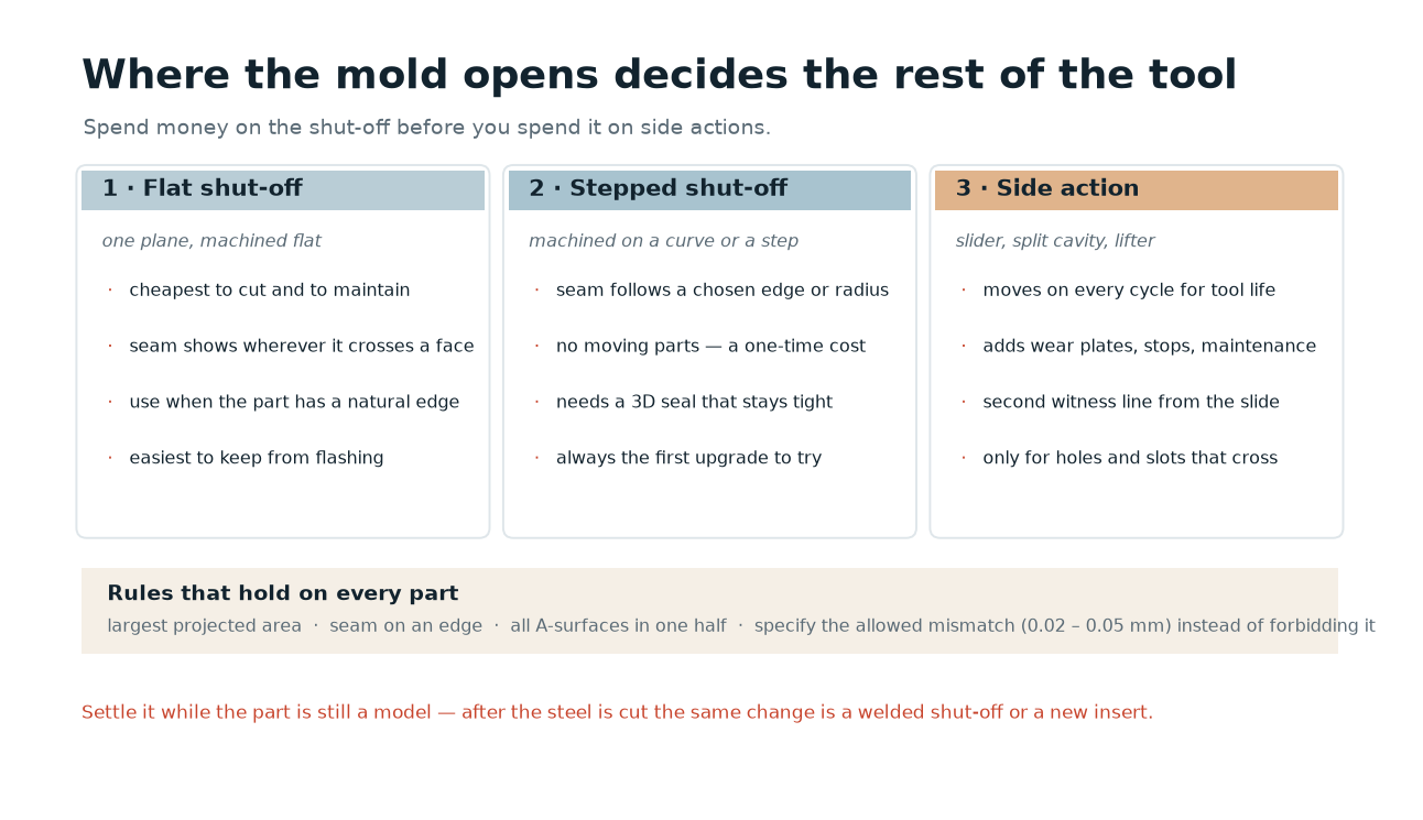
Parting line · one line, five consequences
Parting Line Design: The First Line You Draw Sets Mold Cost
The parting line is drawn early, usually in a hurry, and then everything downstream lives with it: the number of side actions, where flash is allowed to appear, how the part is drafted, and whether the seam lands on a face the customer will photograph.
Ask ten toolmakers where the parting line should go and you will usually get the same answer, but only after they have looked at the part: along the largest projected area, on an edge, with the cosmetic faces in one half. What is worth understanding is why that answer is so consistent, and what it costs when a part cannot follow it. The parting line is not a finishing detail. It is the geometric decision that fixes the rest of the tool.
Five things the parting line decides at once
First, which half of the mold forms which surface. Every surface on one side of the line is formed by the cavity, every surface on the other side by the core. Second, which features become undercuts. A rib, a slot or a hole that crosses the line has to be released by something that moves sideways, and a side action is the single most reliable way to add cost to a tool that was quoted as simple. Third, where flash can appear, and how easy it is to remove without touching a visible face.
Fourth, the draft direction. A surface needs draft measured from the direction it opens, so the parting line sets the direction in which every wall on that side must lean. Fifth, the texture. A grained surface has to be pulled in the graining direction, and if the parting line runs diagonally across a grained face, the texture mismatch at the line becomes the most visible thing on the part.
Flat, stepped or side action
Almost every parting line is one of three shapes, and the trade is always the same: a simpler line means more undercuts to release, a more complex line means a more expensive block of steel and a harder fit.
| Parting surface | Tool cost | Cosmetic risk | Use it when |
|---|---|---|---|
| Flat, single plane | lowest — one shut-off face to fit and maintain | seam visible wherever it crosses a face | the part has a natural flat edge or a hidden split |
| Stepped or contoured | medium — the shut-off is machined in 3D and must seal on a curve | seam moves to a chosen edge, can follow a radius | features sit at different heights, or the seam must dodge an A-surface |
| Split cavity, side core or slider | highest — lifters, sliders, wear plates, extra fitting and maintenance | seam plus a second witness line from the slide | a hole, slot or window genuinely crosses the line |
The rule that comes out of that table: spend money on the parting surface before you spend it on side actions. A stepped shut-off is machined once and then does nothing but seal; a slider has to move on every cycle for the life of the tool, wears, and is the first thing to leak flash after a few hundred thousand shots.
Putting the line where nobody looks
There are five reliable hiding places. On an edge where two surfaces meet at a radius, so the line becomes a tangent break instead of a scar. Under a chamfer or a step, so the mismatch is offset by geometry. At the boundary of a texture change. Behind a part feature that is already a line — a groove, a mating flange, a bead. Or on the non-cosmetic side of an assembly, where the part is never seen once installed.
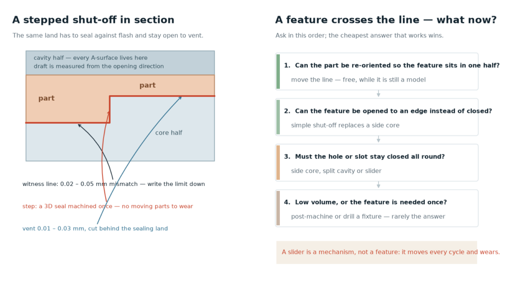
What does not work is putting the line across a gloss face and asking the toolmaker to make it invisible. Two mold halves fitted together will always show a small mismatch: typically 0.02 to 0.05 mm at the shut-off, more on a large tool or after wear. On a matte or grained surface that is hard to see. On a polished black face it reads as a line of light and no amount of polishing removes it, because the two halves are polished separately and then closed. The practical answer is to allow the mismatch, not to fight it: put it somewhere it does not matter, and write the limit on the drawing so that it is measured rather than argued about.
Flash, vents and the seal at the parting surface
The parting surface is also the vent. Air leaves the cavity through a shallow channel cut at the shut-off, usually 0.01 to 0.03 mm deep depending on the resin, opening out to atmosphere a few millimetres behind the edge. That means the same face that must seal against flash has to be deliberately open by a few hundredths of a millimetre in the right places. It is not a contradiction: the vent is cut in the land behind the sealing edge, and a tool that closes perfectly everywhere will burn or short-shot instead of flashing.
Two consequences follow. Vents have to be cleaned, because a blocked vent turns into a flash path under the next injection pressure. And a large flat parting surface on a high-tonnage tool is hard to keep flat: the plates deflect between support pillars and the line opens in the middle. If the part is large and flat, that is an argument for support and for a stiffer mold base rather than for more clamping force. The same logic that decides tonnage applies here: see clamping force and tonnage for the numbers behind it.
When the line has to move
Sometimes the first line does not work, and the fix is cheaper than a slider. A slot near an edge can often be opened to the edge instead of being closed, which turns a side core into a simple shut-off. A hole can be moved a few millimetres so that it sits entirely in one half. A boss can be shortened and picked up by a lifter that was already needed. A window can be molded with a small bridge of material that is cut off afterwards — occasionally the right answer on a low-volume part, and a bad habit on a high-volume one.
The direction of the trade is consistent: change the part, not the tool, while the part is still a model. Once the steel is cut, moving a parting line by two millimetres means welding and re-machining a shut-off, or a new insert. Before that, it is a ten-minute change. This is why the parting line belongs in the DFM review, not in the tool design kickoff — the DFM checklist exists to catch exactly this class of decision while it is still free.
What to mark on the drawing and in the RFQ
A parting line that is not specified is a parting line that will be chosen by whoever builds the tool, usually for machining convenience. Six items are enough to take that decision back:
- the intended parting line, drawn on the model or marked with arrows on a section
- which faces are A-surfaces, and which of them may not carry the witness line
- the allowed mismatch at the line, as a number, and the allowed flash thickness
- the texture grade and the direction it has to be pulled in
- any feature that may not become a side action, and any that may
- the gate position, because gate and parting line are decided together
Two of those items cause most of the disputes in practice: the allowed mismatch, and the texture direction. A drawing that says “no visible parting line” on a polished face is not a specification, it is a hope. A drawing that says 0.03 mm maximum mismatch on the B-surface and 0.05 mm elsewhere can be checked on the bench with a dial gauge, and both sides know before the steel is cut whether the tool passes.
Checking the line before the steel is ordered
Three checks catch nearly everything. Take a section through the part in the proposed opening direction and look for surfaces that are parallel to that direction — they will drag, and no draft angle will save a zero-degree wall. Run a draft check at the line, not on the whole model: the walls close to the shut-off are the ones that decide whether the part releases cleanly. And run the fill simulation with the line fixed, watching where the last material arrives — a weld line that lands on the A-surface is a parting line problem, not a process problem.
If the part is textured, add one more: check that no shut-off runs across the graining direction at an angle. That single check prevents the most common cosmetic complaint on grained parts, and it costs nothing at the model stage. The background on finish grades and how they are specified is in SPI mold finish standards.
The short version
Choose the line along the largest projected area, on an edge, with all cosmetic surfaces in one half. Hide the mismatch rather than forbid it. Prefer a stepped shut-off to a slider. Keep the line out of the vent’s way and the vent out of the sealing land. And settle it while the part is still a model, because the same decision costs a hundred times more after the steel is cut. The geometry on the other side of the line — draft, slides, wall sections — is covered in draft angle, undercuts and mold design and engineering.
Frequently asked questions
Where should the parting line be on a plastic part?
Along the largest projected area, on an edge or a natural break in the geometry, with all cosmetic surfaces formed by one half. That keeps the shut-off simple, keeps the witness line off the faces people look at, and avoids side actions. If the part has no such edge, the next best option is a stepped shut-off that follows a radius or a flange.
Does the parting line affect mold cost?
Yes, more than most part features. A flat single-plane shut-off is the cheapest to machine and to maintain. A stepped or contoured shut-off costs more but is still a one-time cost. A side action adds a mechanism that moves on every cycle — sliders, wear plates, stops and maintenance — and it is usually the largest single cost increase a part can trigger after cavitation.
Can the parting line be invisible?
Not truly. Two mold halves fitted together show a small mismatch, typically 0.02 to 0.05 mm at the shut-off, and it grows with tool size and wear. On textured or matte surfaces it is hard to see; on a gloss face it reads as a line of light. The practical approach is to move it somewhere harmless and to specify the allowed mismatch as a number.
How much flash is acceptable?
As little as the shut-off and the press allow, and the number should be on the drawing rather than agreed verbally. Flash on a visible face has to be removed by hand, which costs money on every part; flash inside an assembly can usually be tolerated. Specify it per surface, not per part, because that is how it will be inspected.
Does the parting line have to follow a flat plane?
No, and often it should not. A stepped or contoured shut-off lets the line follow the part’s geometry, jump between heights, and land on an edge that is already there. The cost is machining a 3D shut-off that must seal along a curve; the benefit is usually one fewer slider and a much better looking part.
What happens if I change the parting line after the steel is cut?
The shut-off has to be welded and re-machined, or the affected area replaced with an insert, and every dependent feature — draft, vents, water lines close to the surface, ejection — has to be re-checked. It is possible, it is slow, and it is the reason the parting line belongs in the DFM review rather than in the tool design kickoff.
Not sure where the seam should land?
Send the part model, the resin and a note on which faces are visible. We will propose the parting line, say what it does to side actions and vents, and tell you which small part changes would remove a slide before the steel is cut.