Design decisions
Mold Flow Analysis: What Simulation Predicts and What Only a Trial Proves
A fill study is a comparison tool, not a certificate. Here is what a simulation can settle before steel is cut, which outputs are worth reading closely, and the six inputs that decide whether the result means anything at all.
Mold flow analysis answers comparison questions, not approval questions. It can tell you that gate layout B will fill more evenly than gate layout A, that a weld line will land in a cosmetic face unless the gate moves, or that the part will want to bow because one side cools faster than the other. It cannot tell you that a tool will pass a dimensional layout, because the model does not know your machine, your dryer, your resin lot or your operator. Read a fill study as a way to eliminate bad options cheaply, and it pays for itself. Read it as proof, and the first trial becomes an argument.
What a fill study is actually for
The value of simulation comes from the cost of being wrong later. Moving a gate after the tool is cut means welding and re-machining a pocket; changing a cooling circuit means re-drilling a plate that may already be hardened; discovering that a 1.2 mm wall cannot be filled at the intended pressure means re-thinking the part, not the tool. All three are cheap on a screen and expensive in steel. That asymmetry is the whole business case.
So the useful question is never “will this mold work” but “which of these three designs survives the same constraints”. A study that compares variants — two gate positions, a hot runner against a cold runner, a baffle against a bubbler — is worth running. A study that predicts one design and declares it good is mostly a document.
There is a second, underrated use: it forces the design conversation to happen early. To run a study you must fix the wall thickness, the gate type, the resin grade and the cosmetic requirement. Half of the arguments that surface at trial are really unresolved inputs that nobody had to name until the model demanded them.
Six outputs worth reading closely
A fill study report can run to forty pages. Most of it is not decision-relevant. These are the outputs that change what gets cut:
| Output | What it actually tells you | How far to trust it |
|---|---|---|
| Fill pattern and last-filled point | Where air will be trapped, which faces will see the flow front last, and whether a short shot is a venting problem or a pressure problem | High — this is the most reliable output in the whole report |
| Injection pressure at transfer | Whether the intended wall section can be filled inside the machine’s usable pressure, with margin for a cold slug or a worn check ring | Medium — depends heavily on the viscosity curve you supplied |
| Weld and meld line position | Where two flow fronts meet, and therefore where the part will be weakest and hardest to paint or texture consistently | High for position, low for visibility — visibility is cosmetic, and cosmetic is judged by eye |
| Temperature at ejection | Which regions are still hot when the tool opens, and therefore which regions will shrink further after ejection | Medium — cooling results are the most sensitive to how the circuits were simplified |
| Volumetric shrinkage and warpage trend | Which direction the part wants to move, and whether the cause is differential cooling, orientation or uneven packing | Direction: useful. Magnitude: treat with suspicion until a trial confirms it |
| Cycle time estimate | The relative cost of two cooling layouts | Relative only — use it to compare, never to quote a number to a customer |
If a report leads with a rainbow warpage plot and no comparison, ask what the alternative looked like. A single deflection picture with no baseline is decoration.
Where the model stops being true
Every simulation is a simplification, and the simplifications cluster in the same six places. Knowing them is what separates a study you can design from and a study you merely file.
- Material data. A generic grade of “ABS” or “PP” in a library is not the grade you will run. Viscosity curves differ between suppliers, and the shear rates that matter in a thin gate are exactly where generic curves are least accurate. Ask for the supplier’s own data sheet, and expect the pressure prediction to move when it arrives.
- Mesh and geometry. Small radii, fine text, texture and draft are simplified or removed. That is normally fine for flow and wrong for anything that depends on a 0.3 mm feature — which is often where a defect shows.
- Inserts, sliders and lifters. Metal inserts change heat transfer locally, and sliders create shut-offs that behave differently from a modelled wall. Models tend to treat them as geometry, not as heat paths.
- The machine. A pressure prediction means nothing without the shot size, the screw diameter, the maximum injection pressure and the actual melt temperature your press can hold. Two machines with the same tonnage can behave very differently on the same tool.
- Venting and surface finish. Air traps are predicted; whether the vent you cut is big enough to let that air out is not. A perfectly filled model with a blocked vent produces a burn mark on the first shot.
- Regrind and lot variation. The model assumes one clean lot. Production rarely does, and a 20% regrind addition shifts viscosity enough to matter on a tight wall.
The inputs that decide whether the study is worth anything
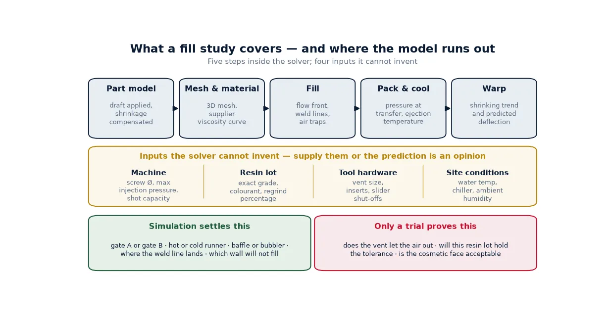
Before a study is run, six things should be on the table. If any one is missing, the result is still useful for comparing options, but not for setting a process window:
- A 3D model with draft applied and shrinkage compensated at the agreed rate — not the customer’s nominal CAD
- The exact resin grade with the supplier’s data sheet, plus the intended colourant or masterbatch
- Gate type and location preference, or an explicit instruction to evaluate more than one
- Machine specification: tonnage, screw diameter, maximum injection pressure, shot capacity
- Cooling constraints: water temperature available on site, circuit count the plate can carry, and whether a chiller is in the plan
- The cosmetic requirement in words — which faces are A-surface, which may carry a weld line, whether the part will be painted or textured
This list is also the reason a study done before the mold design is frozen tends to be more useful than one done after: the inputs are still negotiable, so the answer can still change the drawing.
One thing worth fixing in the design stage: how a part fills is decided by where material enters it, and no amount of process tuning recovers a gate in the wrong place. If the flow front has to travel past a thin rib to reach a thick boss, the thick section will be packed from a distance and the rib will be over-packed — and that shows up later as sink, warpage or flash. The relationship between gate position and those defects is covered in more detail in warpage, sink, short shot and flash.
Reading the report without being fooled by the pictures
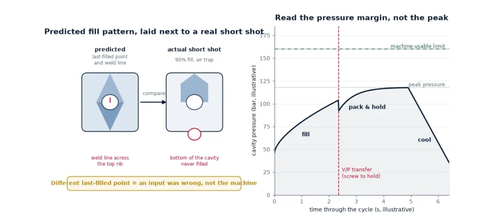
Three habits make a fill study report readable. First, always look at fill time before you look at anything colourful: a fill time plot that shows the last-filled point in a corner is a venting warning, and no pressure setting fixes venting. Second, compare the predicted injection pressure with the machine’s usable pressure, not its maximum — the last 15% of a machine’s rated pressure is not where a stable process lives. Third, check the predicted shot weight against the shot size you intend to run: a part that needs 70% of the barrel is a residence-time problem waiting to appear.
Then look at clamp force. Simulations often predict a clamp requirement comfortably below the machine’s tonnage, which is true for a new tool and less true for a tool with worn parting surfaces. If the prediction sits close to the machine limit, plan for flash control rather than assume it away.
Finally, read the cooling results as trends. Predicted ejection temperature differences between two regions tell you where to put a baffle; the absolute numbers rarely survive contact with a real circuit that has scale in it. This is the same reason cooling circuit design is worth settling on layout principles rather than on a predicted cycle time in seconds.
Where the study changes a tool decision
Four decisions are made materially better with a study in hand:
- Gate location. Moving a gate is the cheapest large change before steel and the most expensive after. A study that shows a weld line landing on an A-surface is worth more than a report that confirms everything is fine.
- Feed system choice. Hot runner or cold runner is partly a volume question, partly a material question and partly a scrap question — the comparison in hot runner versus cold runner sets out the conditions where a hot runner is hard to justify, and a fill study is what confirms which of those conditions you are actually in.
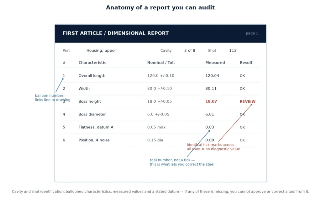
- Cavity count and balancing. On a multi-cavity tool, an unbalanced runner produces parts that differ between cavities — and that difference is invisible until someone measures per cavity. Simulation of a naturally balanced layout is far more reliable than of a modified one.
- Wall section and rib design. Whether a 0.9 mm wall can be filled before it freezes is a question with a numeric answer. Getting that answer before the part drawing is signed is the point.
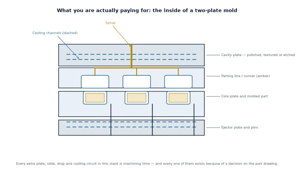
What simulation should not decide is the mold type — a two-plate, three-plate, stack or unscrewing design follows from the part geometry and the volume, and a fill study only tells you whether the feed arrangement that goes with it is workable.
The study and the trial are one loop, not two phases
The most useful thing a simulation does after the tool is built is give the trial something to be checked against. A short-shot series taken at T0 can be laid next to the predicted fill pattern: if the real flow front arrives somewhere else, one of the inputs was wrong — usually the viscosity data, the actual melt temperature or a vent that was not cut. That comparison turns a trial from a negotiation into a measurement, which is exactly the distinction set out in how T0, T1 and PPAP sampling differ.
Conversely, a trial that contradicts a study is not evidence that simulation is useless. It is evidence that one of the six inputs above was assumed rather than supplied. The fix is to correct the input and re-run before the next tool, not to abandon the method.
Frequently asked questions
Is mold flow analysis worth it for a simple part?
For a single-cavity, uniform-wall part with a central gate and no cosmetic requirement, a study mostly confirms what an experienced toolmaker already knows. It becomes worth the time when there is a thin wall, a long flow path, a cosmetic surface, multiple cavities or a warpage requirement — that is, whenever there is a decision to compare rather than a design to confirm.
Can simulation replace the trial?
No. It does not know your machine, your resin lot, your vents or your water temperature. Its useful role is to narrow the options before steel and to give the first trial a baseline to be measured against.
How accurate is the warpage prediction?
Directionally useful, numerically unreliable. It is good at telling you which way a part wants to move and why; it is not good at telling you the millimetres. Treat the magnitude as an indication that needs a trial, and never quote it as a tolerance.
What do you need from me to run one?
A 3D model with draft applied, the exact resin grade with its data sheet, your machine’s screw diameter and maximum injection pressure, and a written statement of which faces are cosmetic. With those four, the pressure and weld-line predictions are usually close enough to design from.
Does a hot runner change what the study shows?
Yes, and it usually improves the prediction, because a hot runner holds melt temperature more consistently than a cold sprue. The model still cannot capture manifold imbalance caused by a worn tip or a heater zone that drifts, which is why hot-runner tools still need per-drop temperature checks at trial.
Reviewing a design before the steel is cut
Send the part model, the resin grade and your machine specification and we will say which features are likely to cause fill or warpage problems, and whether a fill study would change the gate layout.