TROUBLESHOOTING
Injection Molding Defects: Warpage, Sink, Short Shot and Flash
Four defects cover most of what a molder fights. Read the signature, check the cheap causes, and only then decide whether the answer is process or steel.
Warpage, sink marks, short shots and flash account for the large majority of injection molding defects that reach a toolmaker or a molder as a complaint. They look unrelated — one part is bent, another has a dimple, a third is incomplete, a fourth has a thin fin of plastic where the tool should have sealed — but they share a single root: the plastic changed volume at a different rate, in a different place, than the tool assumed when it was cut.
That framing matters because it tells you where to look first. Process settings can compensate for volume change up to a point, and beyond that point no amount of tinkering will help: the tool has to change. The sections below take each defect in that order — read the signature, check the cheap causes, then decide whether you are looking at a process problem or a steel problem.
Read the signature before touching a setting
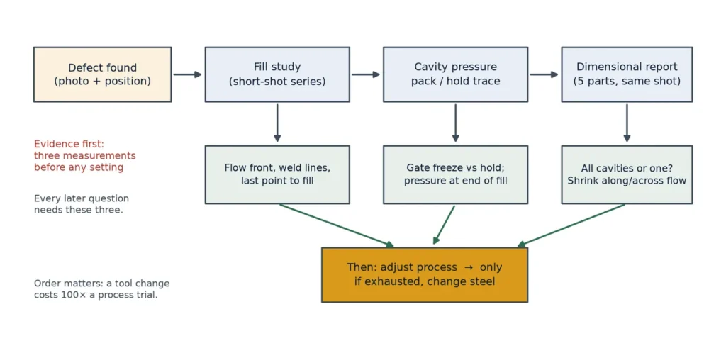
Every one of these defects leaves evidence about where it started. Before a single parameter is moved, get three pieces of information: a short-shot or fill study that shows the fill pattern, a cavity pressure trace through pack and hold, and a dimensional report on the first good parts. Molders who skip this step spend days adjusting temperatures by feel; molders who do it usually find the cause in the first hour.
The table below is the one to keep beside the machine. It maps each defect to the first measurement that separates a process cause from a tool cause.
The measurement side of that list is described on our equipment and quality control page, and the design decisions that remove most of these defects before steel is cut are covered under mold design and engineering.
| Defect | What it looks like | First measurement | Usually process or tool? |
|---|---|---|---|
| Warpage | Part bows or twists after ejection; flatness out of tolerance | Shrinkage measured along and across flow | Either — differential cooling is a tool issue, differential packing is process |
| Sink mark | Local dimple on a thick section or opposite a rib | Wall thickness map; gate freeze time versus hold time | Process first, then rib design |
| Short shot | Incomplete fill at the last point to fill, or a rounded edge | Pressure at end of fill versus machine capability | Process first, then gate and vent |
| Flash | Thin fin at the parting line, ejector pins or slides | Clamp force versus projected area × cavity pressure | Process first, then plate stiffness and vent depth |
Warpage: shrinkage that is not uniform
A molded part warps because one region of it shrank more than another, or shrank in a different direction. Semi-crystalline resins such as polypropylene and polyamide shrink noticeably more along the flow direction than across it, so a part with a strong flow pattern is already asymmetric before any cooling imbalance is added. Amorphous resins warp less from orientation and more from thermal imbalance.
Work through these in order, because each one is cheaper to test than the next:
- Cooling balance. Measure the mold surface temperature on both halves at several points. A 10 °C difference between core and cavity will bow a flat part every time.
- Pack and hold. If the gate freezes before hold ends, the far end of the part is effectively unpacks — it shrinks freely while the near end stays packed. Shorten the flow path, enlarge the gate, or raise the melt temperature so the gate stays open longer.
- Ejection temperature. Ejecting too hot lets the part move while still soft; a fixture or a longer cycle often fixes what looks like a warpage problem.
- Wall thickness variation. Thick-to-thin transitions create a temperature gradient that no packing strategy can remove; if the drawing allows, uniform walls are the real fix.
- Gate location and number. A single gate at one end gives a long, oriented flow path; two gates change the orientation pattern and can reduce bow even though they add weld lines.
When the process window has been exhausted, the tool changes that pay are cooling layout first (baffles or bubbler in cores, conformal channels where the geometry allows), then gate position, then an ejection fixture. A straightening fixture is legitimate production practice for some parts — it is honest engineering, not a workaround, provided it is written into the process sheet.
Where the part geometry leaves room for it, the cooling and gate decisions that prevent differential shrinkage are set during moldflow and process development, not at the press.
Sink marks: the gate closed too early
A sink mark is a local volume deficit on the surface of a part whose interior is still shrinking after the surface has frozen. The classic locations are thick bosses, the far side of ribs, and any section where the wall thickens. The controlling variable is whether the gate is still open and the cavity still packed when that thick section solidifies.
The first check is gate freeze time against hold time. If the gate seals at 2 seconds and the thick section needs 8 seconds to solidify, the last 6 seconds of shrinkage happen with no material to draw from, and the surface pulls in. Raising hold pressure does nothing once the gate is frozen; the useful responses are a larger gate, a hotter melt, or a longer hold with a gate that stays open.
Design-side checks, in the order they repay the effort:
- Rib-to-wall ratio. Ribs at 50–60 % of the nominal wall fill and pack without a visible sink; ribs at the same thickness as the wall almost always show one.
- Boss thickness. A boss wall of 60 % of the nominal wall, with a small core-out, avoids the solid column that causes the dimple.
- Local cooling. A thick section with slow cooling is a sink waiting to happen; a baffle or a high-conductivity insert at that spot is often the cheapest real fix.
- Gas counter-pressure or foaming where the application permits it, which removes the driving force for the sink entirely.
Be careful with the tempting shortcut of packing harder. Over-packing raises internal stress and produces a different defect — warpage or stress whitening — while the sink reappears as soon as the machine drifts.
Short shot: pressure limited or volume limited
A part that does not fill is either asking for more pressure than the machine can deliver at that temperature, or asking for more volume than the shot can supply. The two have different fixes, and the quickest way to tell them apart is the pressure trace at the end of fill.
If the injection pressure is pressed against the machine limit while the screw is still moving, the flow is pressure limited: the melt is too cold, the gate or runner is too small, or the wall is thinner than the flow length allows at that pressure. If the screw reaches its position limit and the part is still short, the shot is volume limited: the cushion at the end of the stroke is too small.
- Venting. Trapped air produces a rounded, sometimes burnt short shot at the last point to fill. A short-shot study that stops just before the end shows whether the flow front is being slowed by back pressure from trapped gas.
- Gate and runner size. Undersized gates are a common cause on tools cut for a different resin; a resin with a higher viscosity needs more gate area for the same fill time.
- Melt and mold temperature. Raising melt temperature 10 °C lowers viscosity enough to finish a fill that was marginal; if that is the only fix that works, the gate area is the real problem.
- Injection speed profile. A faster fill reduces the heat lost to the mold wall; the profile should be set from a fill study, not left at the default.
Short shots near the end of fill are also the cheapest diagnostic in the shop: run the fill study at decreasing stroke and photograph each stage. It tells you the flow pattern, the weld line positions and the last point to fill, which are the three things every other defect investigation needs.
Flash: the tool is not closed, however hard you clamp
Flash appears where the two halves of the tool do not seal: the parting line, around ejector pins, at slide shut-offs and at inserts. The instinct is to add clamp tonnage, and on a stiff tool with adequate platens that sometimes works. On a tool with thin plates or a large projected area it just wears the machine and moves the problem.
Do the arithmetic first. Required clamp force is the projected area of the part plus runner, multiplied by the cavity pressure at the end of packing. A large flat part at 400 bar cavity pressure can need more tonnage than the press has, in which case the answer is lower cavity pressure, a smaller projected area, or a bigger machine — not a longer hold.
Then check the tool itself:
- Parting line fit. Blue the parting surfaces and close the tool; contact should be even and continuous around the cavity. Local gaps show as flash in exactly those places.
- Plate deflection. Support pillars under the cavity plate are not optional on large tools. Without them the plate bows under cavity pressure and the parting line opens in the middle — flash that no clamp force cures.
- Vent depth. Vents that are too deep flash; vents that are too shallow cause short shots and burns. Depth belongs to the resin: roughly 0.02 mm for a low-viscosity resin, 0.04–0.05 mm for a stiff one, with the land short and the vent relieved behind it.
- Ejector and slide fits. A worn ejector bore flashes before the parting line does; check the fit rather than the clamp.
What to send when you ask a toolmaker to look
Most disputes about defects are really disputes about evidence. A toolmaker can act on a short list of facts; without it, both sides guess. Send these:
- Photographs of the defect, with a scale, and the position on the part marked on a drawing.
- The process sheet for the run that produced it: melt and mold temperatures, injection speed profile, pack pressure and time, cooling time, clamp force.
- A short-shot series (three or four stages) and the fill pattern it shows.
- Cavity pressure trace through pack and hold, if the machine can log it.
- A dimensional report on five parts from the same shot, with the measurement points identified.
- Which cavities are affected — all of them, one of them, or a mirrored pair. This single fact often separates a tool problem from a process problem.
With those six items, a defect that has been argued about for a week usually resolves in one conversation. Without them, the toolmaker will ask for exactly this list before doing anything else.
If the conclusion is that the tool has to change, the work falls under CNC machining and prototyping; the tool construction itself depends on which mold type you are running.
Frequently asked questions
Why does my part warp even though the walls are uniform?
Uniform walls remove one cause, not all of them. Check differential cooling between core and cavity, packing that stops when the gate freezes, and shrinkage anisotropy in semi-crystalline resins — flow direction shrinkage can be two to three times the cross-flow figure, which bows a flat part on its own.
Can sink marks be removed by increasing hold pressure?
Only while the gate is still open. Once the gate has frozen, additional hold pressure cannot reach the cavity and the sink will not change. If raising hold pressure has no effect, measure gate freeze time — the fix is a larger gate, a hotter melt or a longer hold with a gate that stays open.
How do I tell a short shot from a burn mark?
A short shot has a rounded, unfilled edge; a burn is a dark or discoloured area, usually at the last point to fill, caused by trapped gas being compressed. Both point at venting, but a burn means the vent exists and is blocked or too shallow, while a short shot may mean no vent at all.
Is flash always a clamp force problem?
No. Clamp force is only one of four causes. The others are a parting line that does not fit, plate deflection under cavity pressure, and vents that are too deep. On large flat parts, plate stiffness is more often the culprit than tonnage.
Which defects should stop a tool from being accepted at T1?
Flash on a shut-off surface, short shots that need process compensation to fill, and sink marks on a cosmetic surface are normally grounds for correction before sampling. Warpage should be measured against the drawing rather than judged by eye, because a part that looks bent may be within tolerance.
How much does the resin itself contribute to these defects?
Significantly. Filler content changes shrinkage and viscosity, and a dryer resin flows differently from a damp one. A defect that appears only with a new resin lot is worth checking against the drying specification and the filler percentage before the tool is touched.