Wall thickness · the number everything else follows
Wall Thickness in Injection Molding: How to Set It and Keep It Uniform
Wall thickness is not a value you pick once and forget. It sets filling, cooling, sink, warpage and the tolerance the tool can hold — and most of the arguments about a part that will not run straight are really arguments about one dimension.
Every drawing review we do starts with the same dimension. Not the tolerance, not the material, not the finish: the wall. Wall thickness decides how far the melt has to travel before it freezes, how long the part sits in the tool, how much clamp force the tool needs, and whether the boss on the inside of the housing pulls a sink mark onto the face the customer looks at. Get the wall wrong and no amount of process tuning fixes it, because the steel was cut around that number.
There is no single correct wall thickness
A wall thickness is chosen against four constraints at once: the melt has to fill the cavity before it freezes, the part has to be stiff enough for its job, it has to survive the impact it will see, and it has to carry the features screwed or snapped onto it. Resin suppliers publish a range rather than a value because the range is what the material allows — the drawing decides where inside that range the part sits.
| Resin | Comfortable wall | Workable range | Flow ratio L/t |
|---|---|---|---|
| PP homopolymer | 2.0 mm | 1.5 – 3.0 mm | ≈ 250 |
| PE-HD | 2.0 mm | 1.5 – 3.0 mm | ≈ 240 |
| PS / HIPS | 2.0 mm | 1.5 – 3.0 mm | ≈ 200 |
| ABS | 2.0 – 2.5 mm | 1.2 – 3.5 mm | ≈ 160 |
| PC/ABS | 2.2 mm | 1.8 – 3.0 mm | ≈ 120 |
| PC | 2.5 mm | 2.0 – 3.5 mm | ≈ 100 |
| PA6 (unfilled) | 1.8 mm | 1.0 – 3.0 mm | ≈ 190 |
| PA66-GF30 | 2.0 mm | 1.5 – 3.0 mm | ≈ 90 |
| POM | 1.8 mm | 1.2 – 3.0 mm | ≈ 140 |
| PBT | 1.8 mm | 1.2 – 3.0 mm | ≈ 130 |
| PMMA | 2.5 mm | 2.0 – 4.0 mm | ≈ 115 |
Two things are worth stating plainly. The numbers are starting points for a drawing review, not limits: a higher-flow grade fills further, a flame-retardant or glass-filled grade of the same polymer does not. And the flow ratio is often the binding constraint — and it is the one most often missing from the drawing.
Thickness is the strongest lever on cycle time
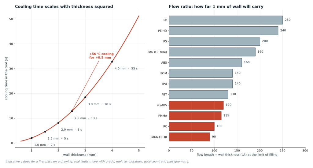
Cooling time in the tool scales with the square of the wall thickness. Doubling the wall roughly quadruples the time the part has to sit in the mold before it can be ejected without deforming. Going from 2.0 mm to 2.5 mm — a change that looks like a rounding decision on a drawing — adds roughly 56 % to the cooling portion of the cycle, on every shot, for the life of the tool. On a part that runs in millions, that is the single most expensive line on the drawing and it is usually decided in an afternoon.
The instinct behind a thick wall is stiffness, and it is the wrong tool for the job. Bending stiffness goes with thickness cubed, so a wall does stiffen quickly as it thickens — but a rib of 0.6 times the wall, standing 3 walls tall, adds more stiffness than the extra material would, and it adds it without the sink mark, without the internal void and without the 56 %.
Thickness also sets clamp force: a part at 2.8 mm instead of 2.2 mm can push the tool onto the next press size, decided once in steel and paid for on every shot. The relationship is set out in the tonnage calculation we use when checking a tool against a machine.
One wall, or a controlled transition
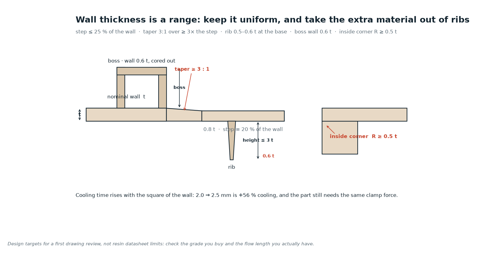
The rule we design to is a 25 % step: adjacent walls should not differ by more than a quarter of the thicker one, and where a step is unavoidable it should be tapered at 3:1 over a length of at least three times the step. What that buys is an even cooling rate across the part. A thick section next to a thin one cools slower, shrinks more, and pulls the thin section with it: the visible result is a sink mark on the cosmetic face or a part that bows when it comes out of the tool.
The classic failure is a housing drawn at 2.5 mm with a 6 mm boss standing on the inside. The boss is a mass of material that stays molten long after the wall has frozen, so the surface above it sinks by 0.1 – 0.3 mm — enough to fail a flatness check and enough to be seen under a gloss finish. Coring the boss to a 0.6 t wall, or moving it off the cosmetic face, solves in the design what no amount of packing pressure solves in the press.
Where a step cannot be avoided, put it close to the gate where the melt is still hot enough to pack it, not at the end of flow. A taper also stops the shear rate spiking as the melt accelerates into the thin section — which matters in glass-filled grades, where a shear spike orients the fibres and leaves a weak line.
Ribs, bosses and the 0.6 t habit
Ribs are the cheapest stiffness in a molded part, and they follow the same rule as bosses: a rib as thick as the wall sinks the face above it. Five numbers cover most rib designs:
- Rib thickness at the base: 0.5 – 0.6 × the adjoining wall
- Rib thickness at the tip: about 0.5 × the base thickness (taper both sides)
- Rib height: up to 3 × the wall before the rib itself needs support or draft becomes awkward
- Rib spacing: at least 2 × the wall, so the material between ribs can still be packed
- Draft on rib sides: 0.5° minimum, more on textured or deep ribs
Bosses follow the same logic: core them out to a wall of about 0.6 t, keep them off the cosmetic face, and add gussets rather than thickening the boss wall. A boss that is solid, or that is thick-walled because a screw needs material, is the most common single source of a sink mark on a molded cover. Where a metal thread is needed, the insert rules cover wall thickness around the insert and the pull-out loads it has to carry.
Flow ratio decides whether the part fills at all
The flow ratio is the longest melt path divided by the wall thickness along that path. Every resin has a practical limit, and past it the melt freezes before the cavity is full: short shots at the far end, higher injection pressure to compensate, and a part that is packed at the gate and starved at the edge. On a drawing the check takes a minute — measure the path from gate to the furthest point, divide by the thinnest wall it crosses, and compare with the resin.
Take a 1.2 mm ABS cover with a 220 mm flow path: L/t ≈ 183, past the practical limit of about 160 for ABS. The answer is not more pressure but a second gate, a thicker wall along the path, or a flow leader — a thicker rib that carries the melt to the far end. Changing a gate layout costs a drawing revision; changing it after the tool is cut costs a cavity insert.
Below 1 mm the tool changes, not just the part
Thin-wall molding is a real technique, but it is not a way to save material on a normal part. At 0.6 – 1.0 mm the melt has to be injected faster than a standard machine and a standard hot runner will deliver, cavity pressure climbs, and the clamp force goes up rather than down. The tool needs higher-strength steel and better support because the cavity sees much higher pressure per unit area, the ejector layout has to be denser because a thin part deforms before it releases, and venting becomes critical because the air has far less time to escape — the venting rules get tighter, not looser.
Below about 0.5 mm the question stops being a molding question and becomes a material and machine one. Above 4 mm the part is usually not a molding part until it is cored: a solid 5 mm section will sink, void, or take a cycle time no quote survives.
Where a wall thickness error shows up later
Wall thickness rarely fails as a thickness callout. It fails as a symptom, two steps downstream, and the symptom is usually blamed on the molder: a sink mark over a boss, a part that bows after ejection, a cavity that will not fill at the end of flow, dimensional drift between the first shot and the hundredth, a break at a weld line. The defect patterns trace back to it, and so does the achievable dimensional tolerance: shrinkage is a percentage of wall thickness, so a wall that varies is a shrinkage that varies, and a tolerance quoted against a nominal wall is only true where that wall actually is.
This is why the wall belongs in the DFM review rather than the toolroom. The DFM checklist we run before cutting steel puts it first for exactly that reason: cheap to change on a screen, expensive to change in a cavity.
Six checks on a drawing before the steel is cut
- Is the nominal wall inside the comfortable range for the resin actually specified, not the resin family?
- Does any adjacent wall differ by more than 25 %, and if so is there a 3:1 taper over at least three times the step?
- Is every rib 0.5 – 0.6 × the wall at the base, and tapered toward the tip?
- Is every boss cored to a 0.6 t wall, away from the cosmetic face, with gussets instead of a thicker wall?
- Does the longest flow path divided by the thinnest wall stay under the resin’s flow ratio — and if not, where does the second gate or the flow leader go?
- Is there any section over 4 mm that could be cored, and any section under 1 mm that was specified for weight rather than function?
Send the wall before the cavity
We would rather argue about a wall thickness on a PDF than in a cavity insert. Send the part drawing or the STEP file with the resin and the annual volume, and we will check the nominal wall, the step transitions, rib and boss ratios and the flow ratio against the gate layout you plan to use — and say which of the six checks above will bite first.
Frequently asked questions
What is the minimum wall thickness for injection molding?
In practice, 1.2 mm is comfortable for unfilled ABS or PP and 0.8 mm is done routinely with higher-flow grades. Below 1.0 mm the tool and the machine have to be built for it — higher injection speed, stronger cavity steel, tighter venting. Below 0.5 mm it stops being a normal molding job.
Can wall thickness vary within one part?
Yes, but in controlled steps: keep adjacent walls within about 25 % of each other and taper any step at 3:1 over at least three times the step. Uncontrolled variation produces sink, voids and warpage, because the thick section shrinks after the thin one has set.
Does a thicker wall make the part stronger?
For impact it helps, for stiffness it is the expensive way to get there. Bending stiffness rises with thickness cubed, but a 0.6 t rib standing 3 t tall adds more stiffness than the extra wall would, without the sink mark and without roughly the squared increase in cooling time that comes with a thicker wall.
How thick should a rib be on a molded part?
0.5 – 0.6 × the adjoining wall at the base, tapering to about half that at the tip, with 0.5° of draft per side and ribs spaced at least 2 × the wall apart. A rib as thick as the wall will sink the surface above it.
What wall thickness should glass-filled PA66 use?
Usually 1.5 – 2.5 mm at a nominal of about 2.0 mm, kept as uniform as possible. Glass-filled grades have a much shorter flow ratio — around 90 — so flow length is often the deciding constraint, and weld lines form weak points where the fibre orientation changes.
Can you mold a 0.4 mm wall?
It is done in thin-wall packaging and connectors, but the tool is built differently: higher-strength steel, heavy cavity support, dense ejection, high-speed injection and a hot runner sized for it. A process decision at the design stage, not a tolerance to push a normal tool to.
Check the wall before the cavity is cut
Send the part drawing or STEP file with the resin and the annual volume. We will review the nominal wall, the step transitions, rib and boss ratios and the flow ratio against the gate layout.