Tool material · aluminum, steel, or one then the other
Aluminum vs Steel Molds: When a Prototype Tool Is the Right Call
The aluminum question comes up early in almost every tooling project. It is not a quality hierarchy — it is a match between the volume, the resin, the tolerance and the finish, and getting it wrong is expensive in both directions.
Almost every RFQ we quote carries a version of the same question: can the tool be aluminum? Sometimes it should be. A 7075-T6 cavity that proves a design with real molded parts before the production steel is cut is often the cheapest place to be wrong. Sometimes it is a trap — an aluminum cavity running glass-filled nylon will wear at the gate, deflect under cavity pressure and let go of the tolerance the drawing asks for, and the money saved on the first tool goes into the second one.
An aluminum tool is a different instrument, not a cheaper steel mold
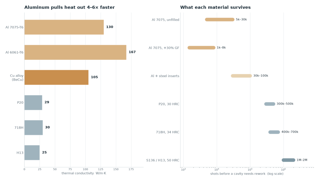
The two materials behave differently in ways that matter more than hardness alone. Aluminum conducts heat four to six times faster than mold steel, which shortens the cycle; it has roughly a third of the elastic modulus, which means a plate that is fine in P20 will deflect in 7075 unless it is supported; and it expands about twice as much per degree, which shows up as tolerance drift on large parts and as wear at shut-offs and parting lines. Read the table as a set of trade-offs, not a ranking. The same geometry rules apply to both materials — mold design and engineering covers what has to be fixed before either cavity is cut.
| Material | Hardness | Thermal conductivity | Typical cavity life | Where it belongs |
|---|---|---|---|---|
| Al 7075-T6 | ≈150 HB | ≈130 W/m·K | 5k – 30k shots | Prototype, bridge, low-volume unfilled resin |
| Al 6061-T6 | ≈95 HB | ≈167 W/m·K | 3k – 15k shots | Simple, thick-walled parts, fast cycles, short runs |
| Al + steel inserts | mixed | ≈130 W/m·K | 30k – 100k shots | Small production runs with wear points protected |
| P20 (1.2311) | 30 HRC | ≈29 W/m·K | 300k – 500k shots | General production tooling, unfilled and filled |
| 718H | 34 HRC | ≈30 W/m·K | 400k – 700k shots | Large cavities, better polishability than P20 |
| S136 / H13 | 48 – 52 HRC | ≈25 W/m·K | 1M – 2M+ shots | Abrasive resin, high volume, fine detail |
What aluminum actually buys you
Three things, and only the first is about money. Heat leaves the part through the cavity wall, and the wall is what limits the cycle: with a cavity running 130 W/m·K instead of 29, the mold face tracks the coolant much more closely, hot spots at thick sections flatten out, and a part that needs 22 seconds in a P20 tool can often come out of aluminum several seconds faster. Second, aluminum is easy to change — a boss moved 2 mm, a rib deleted, a shut-off recut after a fit test is a day of machining, not a new insert. Third, it machines faster, so the first tool reaches T1 with fewer hours in it.
That combination is what makes aluminum the natural material for design validation. You are not buying a tool that will run for five years; you are buying molded parts in the production resin, from the production gate position, before the steel is cut.
Where aluminum loses, and loses quickly
Abrasion is the first limit. Glass fibre, mineral filler and any highly filled grade act like sandpaper on a cavity at 150 HB — the gate, the flow path and the parting line go first, and once the gate has washed out, the fill pattern changes and the parts you were validating no longer represent the steel tool. Hardened inserts at the gate and at high-wear edges are the mitigation, not a cure.
Stiffness is the second. Aluminum’s elastic modulus is about 71 GPa against roughly 205 GPa for mold steel, so at the same plate thickness a cavity deflects about three times as much under the same cavity pressure. Thin cores bend, plates bow between support pillars, and the part flashes at the centre while the edges are fine. The fix is mechanical: thicker support plates, more pillars, shorter unsupported spans — and if the part is large and the pressure high, that arithmetic usually points at steel.
Thermal expansion is the third and the one most often missed. Aluminum expands at roughly 23.6 µm/m·K against 11.5 for steel. A 300 mm span running 40 K above shop temperature grows about 0.28 mm in aluminum and 0.14 mm in steel — a difference of 0.14 mm across one dimension, which is larger than the tolerance on plenty of parts. Small parts are unaffected in practice; large flat parts, long shut-offs and tight centre distances are where it bites, and where the mold temperature has to be held deliberately rather than left to drift.
Finish and detail are the last trade-off. Aluminum takes a good working polish but not a durable mirror on a wearing surface, and fine EDM detail in soft aluminum peens over. If the drawing calls for SPI A-1 to A-2 or a texture that must survive the run, that is a steel decision.
The sequence that makes a bridge tool pay off
The productive way to use aluminum is as a bridge: cut the cavity in 7075, mold T1 and T2 samples, get parts into the customer’s hands for fit, function and drop testing, fix the design in the CAD, then cut the production steel with those corrections already in it. The steel tool is then a second-iteration tool rather than a first guess, and the changes that would otherwise arrive as a repair after T1 arrive as machining before it.
Two conditions keep that from backfiring. The aluminum tool has to be built on the same gate position, the same cooling layout and the same draft as the planned steel tool, otherwise the samples do not predict the production part and the cycle data is worthless. And the volume it will be asked to run has to be decided before the cavity is cut — the common failure is an aluminum bridge tool that quietly becomes the production tool when the forecast turns out lower than planned.
If the tool is going to be aluminum, specify it as a tool
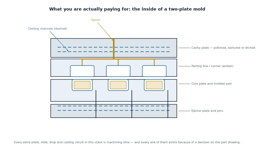
An aluminum cavity built like a steel one, minus the steel, is a short-lived cavity — the same way a two-plate tool built to the wrong standard is. The specification that makes it last is mostly about putting hard material where the wear is and stiffness where the pressure is:
- Hardened steel gate insert and sprue bush — the gate is the first thing to wash out.
- Steel leader pins, guide bushes and return pins; aluminum-on-aluminum guidance wears oval.
- Steel core pins, ejector sleeves and wear plates at every sliding interface.
- Sub-inserts in aluminum for cosmetic and high-wear areas, so a repair is an insert change rather than a new cavity.
- Thicker support plates and support pillars sized for the cavity pressure, not copied from the steel tool drawing.
- Cooling laid out as it will be in the steel tool, with the same circuits and baffles, so the cycle and warp data transfer.
- Production draft, radii and wall transitions — a prototype that only molds because the draft was generous has validated nothing.
What the decision actually reduces to
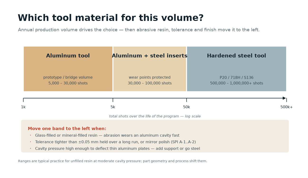
Four questions, in this order. How many parts will this tool really make, including the ones nobody forecast? Is the resin abrasive, and does it need a hard gate? Does the drawing hold a tolerance or a surface that depends on the mold staying put over hundreds of thousands of cycles? And is the design still moving? If the design is still moving and the volume is small, aluminum is the right instrument. If the design is frozen and the volume is real, cutting aluminum first is a detour.
Where the answers are mixed — a stable design at low volume, or an abrasive resin at prototype volume — the answer is usually a steel insert set in an aluminum cavity, which is also the configuration that keeps the wear data honest. On a new part, CNC machining for the prototype usually runs in parallel with the tool decision, so the first samples arrive together.
Frequently asked questions
How many shots will an aluminum mold last?
For 7075-T6 on unfilled resin at moderate cavity pressure, 5,000 to 30,000 shots is the usual working range, and 30,000 to 100,000 is achievable when the gate and wear points are steel inserts and the tool is maintained. Glass-filled resin brings that down to a few thousand at the gate unless it is protected.
Is an aluminum mold cheaper than a steel mold?
Usually yes to build, because the material machines faster and easier — but the comparison only holds if the aluminum tool covers the volume it is asked to run. A tool that has to be replaced inside the program costs more than the steel tool would have, so the decision should be made on volume and geometry rather than on the tooling number alone.
Can an aluminum mold run glass-filled nylon?
It can, for short runs, if the gate and the high-wear flow path are hardened steel inserts and the cavity pressure is kept in check. Without those inserts the gate washes out within a few thousand shots and the fill pattern stops matching the tool you meant to validate.
Can you hold ±0.02 mm in an aluminum tool?
On a small part with a controlled mold temperature, yes at first. Holding it over a long run is the harder part: aluminum expands about twice as much per degree as steel and wears faster at shut-offs, so tolerance-critical, long-running parts belong in hardened steel.
Can an aluminum bridge tool be converted into the production tool?
Not converted — the production tool is a separate cavity. What carries over is everything learned from it: the corrected CAD, the validated gate position, the cooling layout and the cycle and warp data, which is what lets the steel tool start at T1 instead of at a guess.
Does a faster cycle in aluminum also mean less clamp force?
No. Clamp force is set by cavity pressure times projected area, and aluminum deflects more at the same pressure, so the tool usually needs more support and sometimes a lower cavity pressure — not less clamp.
Not sure whether this part needs steel
Send the part drawing or STEP file with the resin, the annual volume and the tolerance that actually matters. We will tell you which of the two tools the project needs, and what changes if the volume turns out lower.