Snap joints · strain before shape
Snap-Fit Design for Injection Molding: Strain, Undercut and Release
A hook that clicks together at the bench and cracks on the third assembly is not a tolerance problem. It is a strain calculation nobody ran, and a loading condition the drawing never stated.
Snap fits are the cheapest fastening method in plastics and a common source of warranty claims we are asked to diagnose on somebody else’s tool. The pattern repeats: a hook that looks reasonable on a 2D print, a resin chosen for the housing rather than the joint, and no number anywhere that says how far the beam is being bent. Run that number before the steel is cut and most snap problems never exist.
Strain at the root decides whether the joint lives
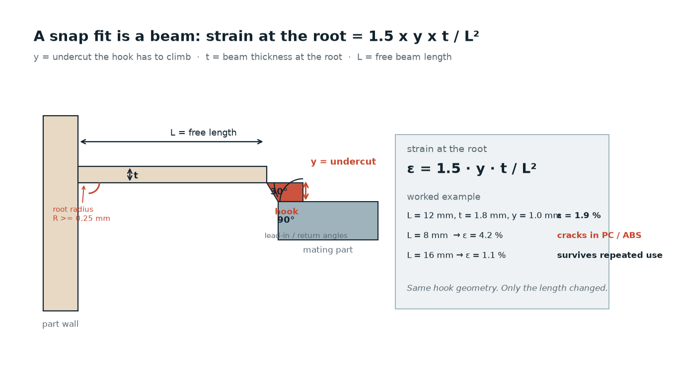
For a cantilever hook with a constant cross-section, the peak strain sits at the root and is given by ε = 1.5 · y · t / L², where y is the deflection the hook has to make to climb its undercut, t is the beam thickness at the root and L is the free length from the root to the point where the load is applied. Three things follow from that expression, and all three are routinely ignored.
First, width does not appear. A wider beam takes more force to assemble but the strain at the root does not change, so widening a hook to make it stronger does nothing for the break. Second, length appears squared, which makes it the most powerful lever on the print: doubling L cuts the strain by four. Third, thickness is linear, so thinning the beam helps, but only in proportion — and thin beams bring their own problems with filling and warpage. When a hook breaks, change the length first.
| Free beam length | Strain at root | In PC or ABS | In PP homopolymer |
|---|---|---|---|
| 8 mm | 4.2 % | over the limit: whitening, then a crack | workable, no margin |
| 12 mm | 1.9 % | at the limit for one assembly only | comfortable |
| 16 mm | 1.1 % | repeated assembly, still fine cold | generous |
| 20 mm | 0.7 % | plenty of margin | may feel soft in the hand |
The table holds thickness at 1.8 mm and the undercut at 1.0 mm: a realistic hook on a 2 mm wall. It is also why two tools with the same nominal design behave differently — one had 16 mm of free beam because the housing allowed it, the other had 8 mm because a boss was in the way.
What the resin actually gives you
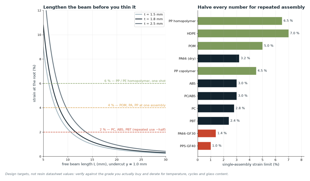
Resin does not set the strain, it sets the budget. The numbers below are design targets we work to, derived from the single-cycle strain limits published in snap-fit design guides and then discounted for real parts, real weld lines and real moulding stress. They are not datasheet values: check the grade you actually buy.
| Resin | One assembly | Repeated assembly | What it means in practice |
|---|---|---|---|
| PP homopolymer | 6–7 % | 3 % | the best snap and living-hinge resin |
| HDPE | 7–8 % | 3.5–4 % | flexible, but creeps under permanent load |
| POM | 4–6 % | 2–3 % | stiff and low friction, good for precise, small snaps |
| PA66, dry | 2.5–4 % | 1.5–2 % | gains toughness as it conditions, design on the dry value |
| PP copolymer | 4–5 % | 2–2.5 % | impact grades trade strain for toughness |
| ABS | 2.5–3.5 % | 1.2–1.7 % | whitens visibly before it fails |
| PC/ABS | 2.5–3.5 % | 1.2–1.7 % | good balance, still notch-sensitive |
| PC | 2.5–3 % | 1.2–1.5 % | notches badly at a sharp root, needs a real radius |
| PBT | 2–2.5 % | 1.0 % | crystalline and brittle, keep the undercut shallow |
| PA66-GF30 | 1.2–1.5 % | 0.7 % | glass turns a snap into a crack initiator |
| PPS-GF40 | 1 % | 0.5 % | avoid snap fits, or make the joint a separate part |
Three deratings sit on top of that table. Glass fibre roughly halves the budget and moves the failure from yielding to brittle fracture. Temperature costs capacity: above 40 °C expect to lose 10–15 % of the allowable strain per 10 °C for amorphous resins, less for semicrystalline ones. Cycles cost the rest — a joint assembled once at the factory can use the upper half of the range, one a technician opens weekly cannot.
Undercut depth, and the two angles that set the forces
Undercut depth y is the engagement, and it is the only dimension that appears both in the strain equation and in retention. Typical engagement is 0.4–1.0 mm on small parts, up to about 1.5 mm on large ones, or roughly 3–5 % of the width of the feature it hooks over. Deeper than that and you are buying retention with strain you do not have.
The two angles do different jobs. The lead-in sets assembly force; 25–30° is the usual range, and going shallower makes the joint easier to close but forces the hook to travel further sideways, which you pay for in strain. The return angle sets release force. A 45–60° return gives a joint that can be opened by hand; a 90° return is effectively permanent because the ramp no longer slides, the mating wall has to deflect instead. As a rule of thumb the release force scales with tan(return) / tan(lead-in), so a 30° lead-in paired with a 60° return takes roughly three times the force to open as to close. If the part is assembled by a robot and opened by a customer, that ratio is a design decision, not an accident.
Can the tool strip the hook, or does it need a slide?
A snap hook is an undercut, and undercuts normally mean a slider, a lifter or a collapsible core — the options and their trade-offs are covered in our guide to undercuts and how to release them. A snap is the one undercut that often does not need any of them, because the hook is designed to bend and can be stripped off the steel at ejection. The question is whether the strain during stripping stays inside the budget.
Stripping works when four conditions hold together: a flexible resin (PP, PE, POM rather than PC, PBT or anything glass-filled); a shallow undercut, generally 1 mm or less; a polished, generously radiused hook with no sharp edge to catch; and ejection with a stripper plate or sleeve rather than pins. Parts also strip better warm than cold. For an annular snap, interference divided by diameter gives a first estimate of hoop strain — 0.8 mm on a 30 mm diameter is around 2.7 %, more at the lead edge. The economics are simple: a slider adds tooling cost and a wear surface that eventually flashes; stripping costs cycle time and puts the hook at risk on every shot. Below about 1 mm in PP, stripping usually wins.
Where the beam goes, and where the gate must not be
A weld line across the root of a snap beam is a crack starter with a stress concentration on top, and it is the single most common reason a hook breaks below the strain its geometry allows. Two habits prevent it. Run the flow along the beam rather than across it, so the molecules orient along the beam axis and the beam gains strength where it needs it; and place the gate so the knit line ends up at the hook tip or on the wall, never at the root fillet. Gate position also decides where the gate blush and residual stress land, and a snap beam is a poor place for either — the same reasoning that governs gate type and gate location everywhere else.
Geometry around the beam matters as much as the beam: a root fillet of at least 0.25–0.5 mm, because a sharp inside corner multiplies the calculated strain; no ribs or bosses stiffening the wall the hook has to deflect; and a lead-in chamfer, because a square edge shaves plastic off the mating part on every closure.
Living hinges are a different animal
A living hinge takes the same idea to its limit: a web thin enough to bend millions of times, molded in the same shot as the two halves it joins. It works in PP homopolymer and, less well, in PP copolymer; it does not work in PC, ABS, PA or anything glass-filled, which crack within tens of cycles. The web is typically 0.25–0.35 mm thick, uniform across its full width, with the gate at one end so the melt sweeps across the hinge rather than shooting along it — molecules oriented across the hinge resist the fatigue crack that runs along it. Keep the steel polished and keep the hinge out of the ejector layout.
Failures at the trial, and what each one tells you
- Whitening at the root before it breaks: the strain is over budget. Lengthen the beam, then thin it.
- A clean break exactly at the root radius: sharp corner, or a weld line sitting there. Add radius, move the gate.
- The joint closes but rattles: engagement too shallow, or the return angle too gentle to hold. Aim for 0.4 mm minimum.
- Assembly force too high for the operator or the fixture: lead-in too steep, or the mating wall too stiff to deflect.
- Fine at 23 °C, fails at −10 °C: resins lose impact strength cold, so derate 30–50 % for low-temperature service.
- Retention drops off over weeks: creep under preload. Leave the joint unloaded at rest instead of designing in interference.
What to put on the drawing and in the RFQ
Most snap disputes are information disputes. The print shows a hook and an angle; nothing states how many times it is assembled, at what temperature, or whether it is meant to come apart. Supply these and the strain check takes minutes instead of a trial:
- Free beam length, thickness at the root, undercut depth, root radius, lead-in and return angles.
- Resin, grade and glass content, and whether the part will be conditioned before use.
- Assembly cycles expected, and the service temperature range including storage and transport.
- Whether the joint is permanent or serviceable — that single answer sets the return angle.
- What carries the load: the snap alone, or the snap plus screws or an adhesive.
A snap fit costs almost nothing to mold and a great deal to fix after the tool is cut, because the fix is usually a longer beam — which means steel that was not there. If you are designing a housing around one, send the hook geometry and the resin and we will run the strain check against the tool layout before the cavity is machined. The broader pre-cut review is in our DFM checklist; the release-side dimensions follow the same logic as draft angle, and how much the plastic moves around the hook is covered in shrinkage and dimensional tolerance.
Frequently asked questions
How do I calculate the maximum deflection of a snap-fit hook?
For a constant-section cantilever, strain at the root is 1.5 × y × t / L², so the maximum deflection for a given allowable strain is y = ε × L² / (1.5 × t). Decide the resin budget first, then solve for the beam length — length is the cheapest thing to change on a print.
How deep should a snap-fit undercut be?
0.4–1.0 mm of engagement on most small and medium parts, up to about 1.5 mm on large ones, or roughly 3–5 % of the width of the feature it hooks over. Every millimetre of extra depth is extra strain at the root, so depth should be set by the retention you actually need.
Can a snap fit be molded without a slider?
Yes, when the hook can be stripped at ejection: flexible resin such as PP, PE or POM, undercut around 1 mm or less, a polished and radiused hook, and a stripper plate or sleeve instead of ejector pins. In PC, PBT or glass-filled resins the same undercut usually needs a slider, a lifter or a redesign.
Why did my snap fit crack on the first assembly?
Four usual causes, in order of frequency: beam too short for the undercut, thickness too high at the root, a weld line sitting at the root because of gate position, and a sharp inside corner. Glass-filled resin makes all four worse, and all four are visible before the tool is cut.
What lead-in and return angles should a snap fit use?
A 25–30° lead-in for assembly, then a return angle chosen by intent: 45–60° to open by hand, 90° for a joint that never comes apart. Release force scales with tan(return) / tan(lead-in), so choose the pair together.
Do snap fits work in glass-filled resins?
Poorly. Glass roughly halves the allowable strain and changes the failure from yielding to brittle fracture, so the hook snaps instead of bending. If the housing needs glass for stiffness, make the snap a separate unfilled part, or replace the snap with a screw boss.
Run the strain check before the cavity is cut
Send the hook geometry, the resin and how many times the joint is assembled. We will check beam length, root strain and stripping against the tool layout.