GATING
Gate Types and Gate Location in Injection Molding: What the Gate Decides Before Steel Is Cut
The gate sets the fill pattern, where the weld line lands, how long the part packs, and what somebody has to cut off afterwards. Choose the family from the part, the size from the wall, and the position from flow length — in that order.
A gate is the smallest deliberate restriction in the whole flow path, and it controls more of the outcome than any other single feature of the tool. It decides where melt enters the cavity, so it decides the fill pattern and the position of every weld line. It decides how long the part keeps packing before the gate freezes, so it decides sink and internal stress. And it decides what is left on the part when the tool opens — a vestige to be trimmed, a mark to be hidden, or nothing at all. Because all three of those are fixed in steel, gate decisions are expensive to revisit. Get them right on the drawing, and the trial becomes a process exercise instead of a tool modification.
What a gate controls, in order of consequence
It helps to separate what the gate genuinely sets from what it merely influences. The gate sets the entry point and therefore the flow front geometry. That fixes where weld lines form and where air is trapped, which is why venting and gating are designed together rather than one after the other. The gate also sets the shear rate at entry: too small and the melt is over-sheared, which shows up as splay, flow marks or burnt streaks, especially in polycarbonate and other shear-sensitive resins. And the gate sets the freeze time, which caps how long the packing phase can act on the cavity — the reason a gate that is marginally too small produces sink at the far end of a thick part even when the press is doing exactly what the process sheet asks.
What the gate does not decide is cooling. Cycle time follows the thickest wall and the cooling circuit far more than the gate, although a restricted gate can add a little to the cycle when the pack time has to be extended to compensate. If you are chasing cycle, start with the cooling circuit design before you go looking at the gate.
The gate families, and what each one leaves behind
| Gate type | Where it sits | Suits | What it leaves on the part |
|---|---|---|---|
| Sprue (direct) | Melt enters the centre of the part straight from the sprue bush | Large single parts, thick sections, low cavity count | A large sprue stub to cut and finish; long cooling at the sprue |
| Edge / side | Along the parting line into the part edge | Flat parts with an accessible edge, multi-cavity tools | A small tab to trim; a witness mark on the edge |
| Fan | A widening land along the edge | Thin flat parts prone to jetting or flow marks | A thin film along the edge, trimmed after moulding |
| Tab | Onto a sacrificial tab that is trimmed later | Parts where a gate mark at the edge is not acceptable | Nothing on the part itself; the tab carries the mark |
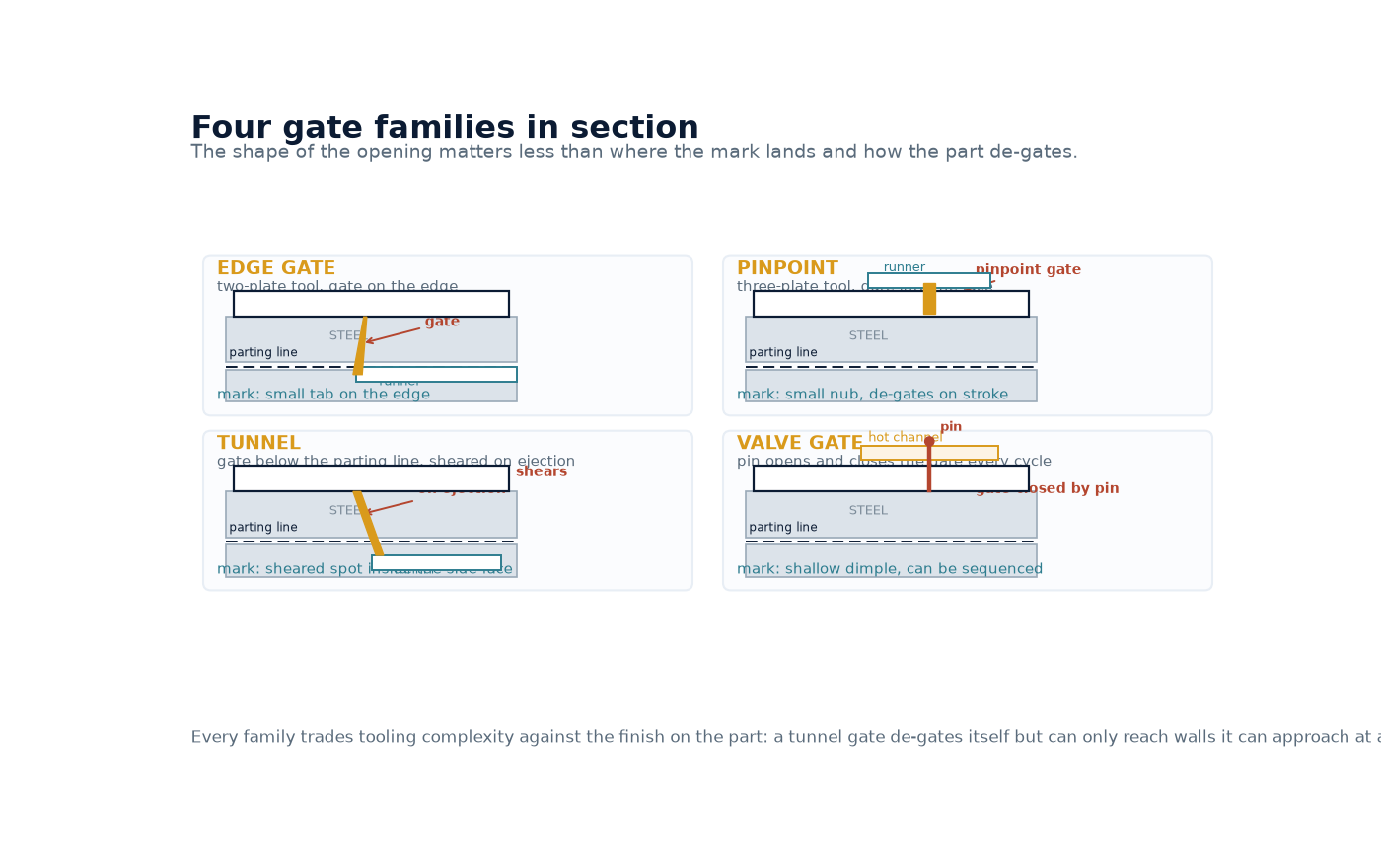
| Pinpoint | A small round gate into the cavity, usually from a three-plate tool | Small and medium parts, multi-cavity layouts, centre feeding | A small nub; three-plate tooling adds a de-gating stroke |
| Tunnel / submarine | Below the parting line, into a side wall, sheared off on ejection | Two-plate tools where automatic de-gating is wanted | A sheared mark inside the side face; gate can only reach certain walls |
| Hot tip (insulated) | A heated tip that keeps the melt molten between shots | Engineering resins, small gates on visible surfaces | A small gate vestige; thermal sensitivity in the tip area |
| Valve gate | A pin opens and closes the gate positively each cycle | Large parts, thick sections, sequential filling, cosmetic surfaces | Almost nothing, and it can be opened and closed by sequence |
Two practical points sit behind that table. First, every family trades tooling complexity against the finish on the part: a tunnel gate de-gates itself but can only reach walls it can approach at an angle, and a three-plate tool buys you a centre pinpoint gate at the cost of an extra plate and a longer opening stroke. Second, the hot-runner question is usually settled before gate type is: whether to run a hot or cold feed system is a separate decision with its own economics, covered in hot runner vs cold runner.
Choosing the family from the part
Work outward from the part rather than inward from a gate you used last time. Four questions usually settle the family:
- How thick is the wall at the gate? Very thin walls rule out small pinpoint and tunnel gates, because the shear rate at entry climbs as the gate shrinks.
- Does the part have a cosmetic face that cannot take a mark? That point alone pushes you toward tab gating, a hidden edge, or a valve gate on the non-cosmetic side.
- Does the tool need to de-gate automatically? High-cavity-count tools and lights-out running justify tunnel gates or a hot-runner system.
- Is the resin shear-sensitive? Polycarbonate, PMMA and some high-viscosity blends punish restrictive gates with splay and stress marks, which argues for a larger gate or a valve gate.
Gate size: start from the wall, then check the freeze
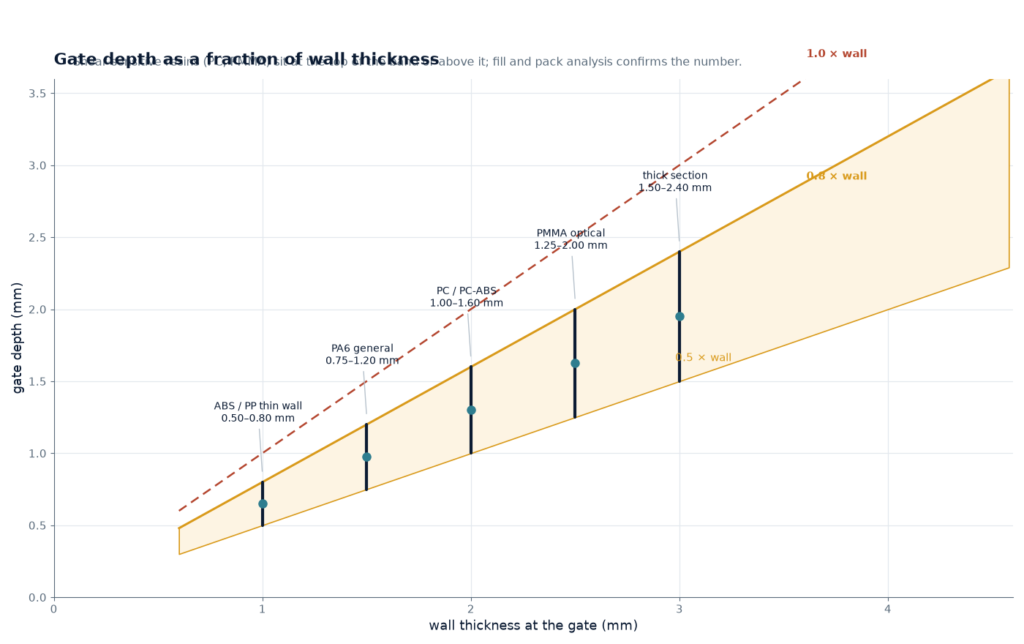
Gate depth is normally set as a fraction of the wall thickness at the gate, and the fraction moves with the resin and with how much packing the part needs. As a starting point, gate depth runs around half to four-fifths of the adjacent wall, with the land kept short. Anything much below half the wall freezes early and stops transmitting pressure, whatever the hold time says.
| Resin family | Starting gate depth | What to watch |
|---|---|---|
| ABS, HIPS, PP, PE | 0.5–0.7 × wall | Forgiving; a slightly restrictive gate mainly costs packing at the far end |
| PA6, PA66 (unfilled) | 0.6–0.8 × wall | Low viscosity fills easily, but freeze is fast — check pack time on thick sections |
| PA with glass fibre | 0.7–0.8 × wall | Fibre orientation at the gate drives warp; gate position matters as much as size |
| PC, PC/ABS | 0.7–0.9 × wall | Shear-sensitive: small gates show splay and stress marks rather than short shots |
| PMMA, optical grades | 0.8–1.0 × wall | Any gate mark is a defect; plan for a tab or valve gate, not a smaller gate |
| POM | 0.6–0.8 × wall | Narrow processing window; gate freeze and cycle interact strongly |
Treat the table as a starting point and confirm it against a fill and pack analysis, because the number that matters is not the depth itself but the shear rate and the freeze time it produces on your part. A gate that is generous by the table but sits at the end of a long thin flow path is still the wrong gate.
Gate location: five rules worth applying in order
Location is where most avoidable defects come from, and the rules are old because they work:
- Feed the thickest section first. Melt should travel from thick to thin, so the thin end packs while the gate is still open, and the thick end is not starved.
- Keep flow length inside what the resin allows at the available pressure. If the ratio of flow length to wall thickness is marginal, add a gate rather than raise the pressure.
- Put weld lines where they cannot hurt: away from cosmetic faces, away from impact zones, and ideally where they can be vented.
- Aim the gate at a wall or a pin, not into open space. A free jet into a cavity produces jetting, and jetting produces a cold slug line that no process setting removes.
- Check that the gate can be trimmed or sheared without touching a sealing surface, a thread, or a face the customer will see.
Defects that are really gating decisions
| What you see | Typical gate cause | First change to try |
|---|---|---|
| Jetting / snake-like mark | Gate aimed into open cavity, or gate too small for the fill rate | Aim at a wall or pin; enlarge the gate; adjust fill rate |
| Splay or silver streaks | Shear at a restrictive gate, or moisture in the resin | Enlarge the gate, then dry the resin before changing anything else |
| Sink at the far end of a thick part | Gate freezes before packing finishes | Increase gate depth, extend hold, or move the gate closer |
| Weld line in a cosmetic area | Gate position sets where flow fronts meet | Move the gate, or add a overflow well so the weld forms off the visible face |
| Warpage after ejection | Gate position drives orientation and differential packing | Move the gate to balance flow, or change fill pattern with a sequenced valve gate |
| Gate blush around the entry | High shear at a small gate, or fast injection | Enlarge the gate and profile the fill; check the gate land length |
Reviewing the gating before the steel is cut
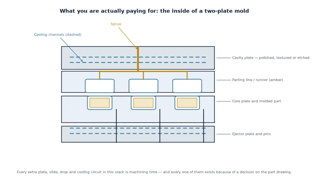
The review that pays for itself is a single page: gate family, gate location, gate depth, weld line position, expected vestige, and how the part will de-gate. Take it to the DFM review and check it against the DFM checklist, because gating problems and wall-thickness problems are usually found in the same meeting. If the part is a family of variants, do this for the most demanding variant, not the average one. Our overview of mould types explains which of these gate families each tool construction can physically carry, and the defect guide covers the symptoms side of the same story.
One last discipline: agree the gate mark with whoever owns the cosmetic requirement, in writing, before the tool is cut. A gate vestige that a designer considers invisible and a moulder considers normal is exactly the sort of disagreement that turns a good trial into a steel change.
Frequently asked questions
Can the gate be changed after the tool is built?
Often yes, within limits. Enlarging a gate is a straightforward sparking or milling job. Moving it means welding and re-cutting, which risks the surrounding steel and the cooling lines, so it is done only when the defect cannot be solved any other way. Changing gate family usually means changing the tool construction, which is why the family is worth getting right on the drawing.
Is a bigger gate always safer?
No. A generous gate packs better and shears the melt less, but it also freezes later, which can extend the cycle and leave a larger vestige to trim. The useful rule is to size the gate so it stays open long enough to pack the part, and no longer.
How many gates should a part have?
As many as the flow-length limit requires and no more. Each additional gate adds a weld line, so multi-gating trades filling capability for weld lines. Where a single gate can fill the part within the resin’s flow-length ratio, one gate gives the cleanest result.
Does a hot tip gate leave a mark?
It leaves a small vestige at the tip, typically a shallow dimple or a slight ring, and the size depends on the tip diameter and the resin. On visible surfaces the usual approach is to place the tip on a non-cosmetic face or accept the mark by agreement, rather than to chase a mark-free gate.
Why does the weld line appear where the drawing did not put it?
Because the gate position and the part geometry together decide where flow fronts meet, and the meeting point moves with fill rate and with small wall-thickness differences. Plot the weld line from a fill analysis rather than from the drawing, then confirm it on the trial part before polishing anything.
Can gate location fix warpage?
It can change it, which is not the same thing. Gate position drives fibre orientation and differential packing, so moving a gate redistributes warp rather than removing it. Warp is normally settled by combining gate position, cooling balance and, for glass-filled resins, part and rib design.
Send the part drawing before the gate is fixed
Tell us the resin, the wall at the intended gate and the faces that must stay mark-free. We will come back with a gate family, a gate size starting point and the weld line position we would expect, so the DFM review starts from a proposal instead of a blank page.