VENTING
Mold Venting Design: Vent Depth, Location and the Burns That Prove It Wrong
Air leaves before resin arrives, or it does not leave at all. Vent depth is measured in hundredths of a millimetre and changes with the resin — and the burn mark on the part is usually the receipt.
Vent a mould where the air actually is — the last place to fill, the end of every runner, the top of every deep rib and behind every slide — and cut the depth to the resin rather than to habit. In practice that is a 0.010–0.040 mm deep land, 3–5 mm long, opening into a relief channel 0.3–0.5 mm deep that reaches the outside air, repeated often enough around the parting line that the total vent area can pass the displaced air in the fill time. Get the depth wrong on the deep side and you get flash you cannot polish out; get it wrong on the shallow side, or block it, and you get burns, short shots and a process that needs more pressure than the part deserves.
What is actually happening during fill
The cavity contains air at atmospheric pressure. As melt enters, that air has to go somewhere: out through the vents, out through clearances, or into solution in the polymer. It does not compress politely. Air trapped in a dead end is compressed by the incoming melt, and compression heats it — the diesel effect. A pocket compressed to a fraction of its volume can reach several hundred degrees Celsius, which is enough to char the resin surface and leave the brown-to-black deposit that everyone recognises as a burn mark.
That is why the burn mark is diagnostic rather than cosmetic. It marks the place where air could not leave. Its position tells you which vent is missing or blocked, and how much of the fill was lost to back pressure. It also means polishing the mark away and running the job again changes nothing: the cause is still there, in the steel, one layer down.
Vent depth by resin
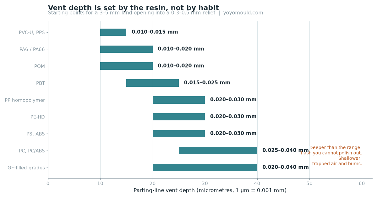
The usable depth scales with melt viscosity: the thinner the melt, the shallower the vent has to be before it flashes. The ranges below are starting points for a parting-line land of 3–5 mm. Every one of them should be confirmed on the tool and adjusted after T1 rather than taken as a specification.
| Resin | Vent depth | Notes |
|---|---|---|
| PVC-U, PPS | 0.010–0.015 mm | Thin melt, aggressive to steel; vent generously, shallow |
| PA6 / PA66 | 0.010–0.020 mm | Low viscosity; vents block with deposit |
| POM | 0.010–0.020 mm | Flash-prone; shallow land, wide area |
| PBT | 0.015–0.025 mm | Crystalline, fast fill, hot spots at rib tops |
| PP homopolymer | 0.020–0.030 mm | Wide processing window, tolerates depth |
| PE-HD | 0.020–0.030 mm | Same; watch flash on high packing |
| PS / ABS | 0.020–0.030 mm | Common starting point for cosmetic parts |
| PC / PC-ABS | 0.025–0.040 mm | High viscosity; deeper vent, still lands short if blocked |
| Glass-filled grades | 0.020–0.040 mm | Fibres bridge shallow vents; widen rather than deepen |
Vent geometry: three dimensions and one area
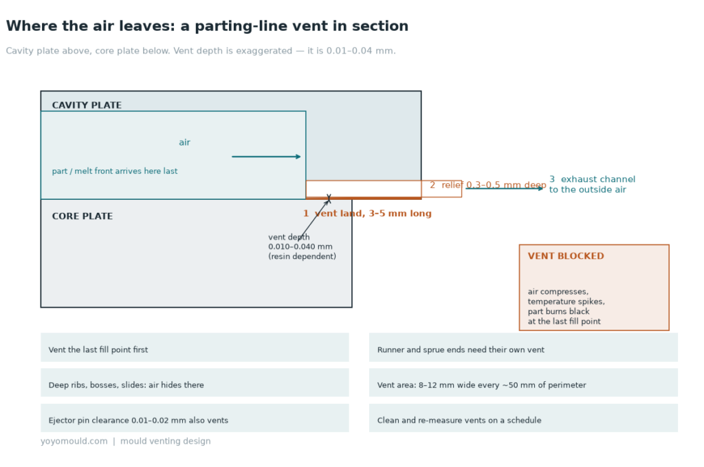
A vent is not a groove. It is a shallow land whose depth controls flashing, followed by a deeper relief whose job is to move the air away, followed by an exit to atmosphere that is not blocked by a clamp face, an ejector plate or a water line. Many tools have the first and forget the second, which is why a vent that measures correct on the bench does nothing in the press.
- **Land depth** 0.010–0.040 mm by resin — the flash-critical dimension.
- **Land length** 3–5 mm — long enough to resist flash, short enough to have low resistance.
- **Relief channel** 0.3–0.5 mm deep, 3–6 mm wide, behind the land, not in place of it.
- **Vent area** wide enough to matter: several 8–12 mm wide lands around the perimeter, not one, and one at every place air is trapped.
Where the air hides
Venting the whole parting line is necessary but not sufficient. Air collects in dead ends, and a dead end is any feature that fills last. The list is short and worth walking through on the drawing before the cavity is cut, because most of these are cheap now and awkward later.
- **Last fill point** — the single most important vent on the tool.
- **Runner and sprue ends** — cold-slug wells need a vent behind them or they hydro-lock.
- **Top of deep ribs and bosses** — the classic burn-mark site on tall, thin features.
- **Behind slides and lifters** — moving steel seals the air in unless it is vented.
- **Ejector pins and sleeves** — 0.01–0.02 mm clearance vents, but leaves witness marks.
- **Insert and split lines** — interfaces that look tight still leak air slowly.
- **Sprue puller and runner ejector pins** — often forgotten on a hot-runner tool.
- **Porous steel inserts** — for deep, narrow features with no parting line to reach.
Reading the symptom
| What you see | What it usually means | First check |
|---|---|---|
| Black or brown burn at one spot | Air compressed at a dead end | Vent depth and cleanliness at that spot |
| Silver streaks near the gate | Moisture or shear, not always air | Dryer and melt temperature before vents |
| Short shot at the far end | Back pressure from trapped air | Vent area and fill speed |
| Weak weld line | Air or cold melt at the join | Vent at the weld, then gate position |
| Flash on the parting line | Vent too deep, or packing too high | Measure the land, then the clamp |
| Progressive burns over a run | Vent filling with deposit | Cleaning interval |
The distinction between air and moisture matters because the fixes point in opposite directions. Air problems get worse as fill speed rises, because there is less time to vent. Moisture problems look similar but follow the dryer, not the tool. When both are present — a wet resin in an unvented tool — the burns look severe and the dryer gets blamed for a venting fault. The defects overview is a reasonable place to start separating them.
When the parting line is not enough
Some geometry leaves nowhere to vent: a deep blind rib in the middle of a core, a long thin core pin, a part that fills from the centre outwards into a sealed ring. There are three answers. Sintered metal inserts let air pass through the steel itself and are the neatest solution for small, hot areas, though they clog and need cleaning on a schedule. Ejector-pin clearance is free venting that already exists, provided the clearance is right and the pin is not in a cosmetic face. Vacuum venting, where the cavity is evacuated before the shot, is the industrial answer for very large parts or very fast fills, and it turns venting from a geometry question into a maintenance question.
A hot runner adds its own case: the manifold and nozzle bodies displace air with each shot, and a tool with twelve drops and no venting at the drop seats will burn at the drop seats. This is one of the practical differences between hot runner and cold runner that does not appear in the cost comparison: a hot-runner tool has more places where air gets trapped, and they are all in the steel.
Vents are a maintenance item
A vent that measured 0.020 mm at build can be 0.005 mm six months later, because mould deposit fills the shallowest feature on the tool first. That is not a defect, it is a schedule. Clean the lands with brass or copper — never with abrasive paper, which rounds the edge that makes the vent work — check the depth with a gauge or an impression, and record the readings in the same log as the ejector and slider checks. A tool that starts making occasional burns and recovering on its own is telling you the vent is closing, not that the resin changed.
This is why venting belongs in the maintenance schedule rather than in the commissioning report, and why it belongs in the DFM review as well: where the air goes decides where the vent lands, and that decision is much easier to make on a drawing than on a finished core.
What to send for a venting review
- Part drawing with the gate position marked, or a flow study showing the last fill point.
- Resin grade, including filler content and flame-retardant package.
- Any existing burn, short-shot or flash photos, with the location on the part marked.
- Cavity count and tool structure (two-plate, three-plate, hot runner, slides).
- Whether the part is cosmetic on the faces where ejector-pin venting would leave marks.
- Fill time the process is expected to run at — vent area has to match it.
Frequently asked questions
How deep should a vent be for glass-filled PA66?
In the 0.020–0.040 mm range, wider rather than deeper. The base resin would tolerate a shallower land, but glass fibres bridge narrow gaps and the vent stops working almost immediately. Widening the land and adding more of them is the safer direction than cutting deeper, because depth is what decides whether the part flashes.
Can ejector pins be used as vents?
Yes, and they already are whether or not anyone planned it. A clearance of 0.01–0.02 mm vents effectively. The limits are cosmetic: the clearance leaves a witness ring, and if the pin sits on a visible face the mark will be rejected. They also wear, so the clearance grows and the venting with it — which is how a tool that never flashed starts to.
The vent measures correct but the part still burns. Why?
Usually because the air cannot get from the vent to atmosphere: a relief channel that stops at a clamp face, a vent that terminates in a water line pocket, or a vent on the parting line where the press closes it off. The other common cause is vent area — one land on a large part is not enough for the fill speed, so the air is still compressed no matter how clean the land is.
Does vacuum venting remove the need for vents?
It removes most of the trapped air before the shot, which helps enormously on large or fast-filling parts, but it does not remove the need to let the remaining air and the gases produced by the melt escape. It also adds seals, a pump and a leak check to the maintenance list. It is a good answer for a specific problem, not a replacement for a normal venting layout.
Will a deeper vent cause flash?
Beyond the range for that resin, yes — flash appears first where the melt is thinnest and the packing is highest, and a flashed vent gets worse because the flash itself holds the plates apart. That is why the land, not the relief, is the dimension to control, and why the depth should be measured rather than estimated from how it looks.
Chasing burn marks or short shots on an existing tool?
Send the part, the resin grade and a photo of where the defect sits. We will tell you which vent is missing or blocked, and whether the fix is a vent, a gate change or a process window that was never there.