SHRINK & TOLERANCE
Injection Mold Shrinkage and Dimensional Tolerance: What a Mold Can Actually Hold
Shrink is a range per resin, not a constant, and it is different along the flow than across it. Set the allowance from wall and gate, then agree tolerance against size — in that order.
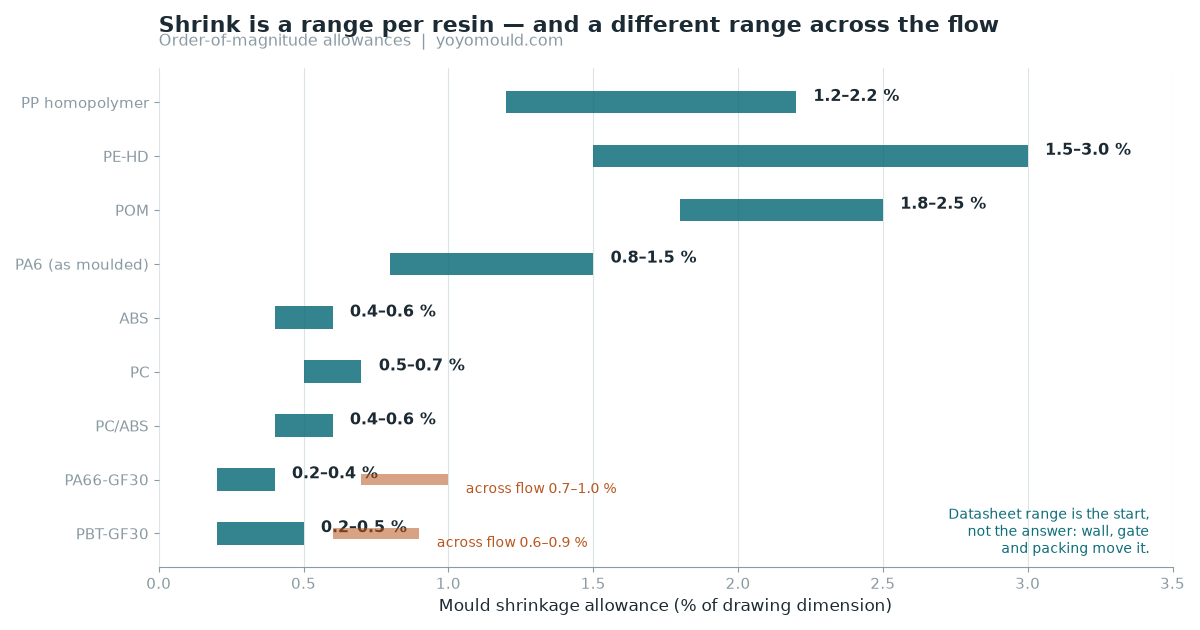
Cut the tool to a shrink allowance you can defend, then agree tolerances against part size — not the other way round. Shrinkage is a range, not a resin constant: ABS sits around 0.4–0.6 %, PP around 1.2–2.2 %, POM around 2 %, and a 30 % glass-filled polyamide shrinks roughly 0.2–0.4 % along the flow but 0.7–1.0 % across it. A mould cut to the middle of the range, with the dimensions that matter marked for correction after T1, lands in specification. A mould cut to one nominal number, with drawing tolerances borrowed from the machined metal part next to it, does not — and by the time the parts are measured, the steel is already hard.
Why shrink is a range and not a number
Shrinkage is the difference between the cavity and the part after it has cooled and stabilised. It is driven by four things at once: how much the polymer densifies as it cools, how much material was packed in before the gate froze, how the wall thickness let heat out, and which direction the molecules or fibres ended up aligned in. Change any one of them and the number moves — which is why the same resin appears with 0.4 % in one datasheet and 0.8 % in another. Both are correct; they were measured on different walls.
Semi-crystalline resins (PP, PE, POM, PA, PBT) shrink more than amorphous ones (ABS, PC, PS, PMMA) because crystallisation packs the chains tighter. They are also more sensitive to mould temperature: a hotter mould lets crystallisation run further, and the part comes out smaller. Amorphous resins are comparatively flat, which is why tight-tolerance work often ends up in PC or ABS even when another resin would be cheaper per kilo.
- **Thicker wall** → more shrink; a 4 mm PP wall can run a full point above a 2 mm wall.
- **Higher packing pressure and longer hold** → less shrink near the gate, more differential shrink far from it.
- **Hotter mould** → more shrink in crystalline resins, almost nothing in amorphous ones.
- **Higher melt temperature** → slightly more shrink, mostly through better relaxation.
- **Fibre orientation** → less shrink along the flow, more across it, and a warp that follows.
Order-of-magnitude allowances by resin
The numbers below are starting points for a normally packed part with a wall between roughly 1.5 and 3 mm. Treat them as the middle of a band you will narrow with a mould flow study or a sample, not as a specification.
| Resin | Typical shrink | Across flow | What moves it most |
|---|---|---|---|
| ABS | 0.4–0.6 % | ≈ same | Packing pressure, gate freeze |
| PC / PC-ABS | 0.5–0.7 % | ≈ same | Melt temperature, internal stress |
| PP homopolymer | 1.2–2.2 % | ≈ same | Wall thickness, mould temperature |
| PE-HD | 1.5–3.0 % | ≈ same | Wall thickness, density grade |
| POM | 1.8–2.5 % | ≈ same | Mould temperature, gate size |
| PA6 / PA66 (dry) | 0.8–1.5 % | ≈ same | Moisture after moulding, wall |
| PA66-GF30 | 0.2–0.4 % | 0.7–1.0 % | Fibre orientation, gate position |
| PBT-GF30 | 0.2–0.5 % | 0.6–0.9 % | Fibre orientation, wall |
Two entries deserve a warning. Polyamide keeps shrinking after it leaves the machine, then grows again as it absorbs moisture in service; the mould allowance is therefore set below the as-moulded figure — often 0.4–0.8 % — and the dimension is only meaningful after conditioning. Glass-filled grades are worse in a different way: the number is not one number at all, it is a direction, and the difference between the two directions is where warpage comes from. This is the same reason warpage, sink and short shot so often trace back to gate position rather than to the cooling circuit.
Tolerance: what a steel tool holds against size
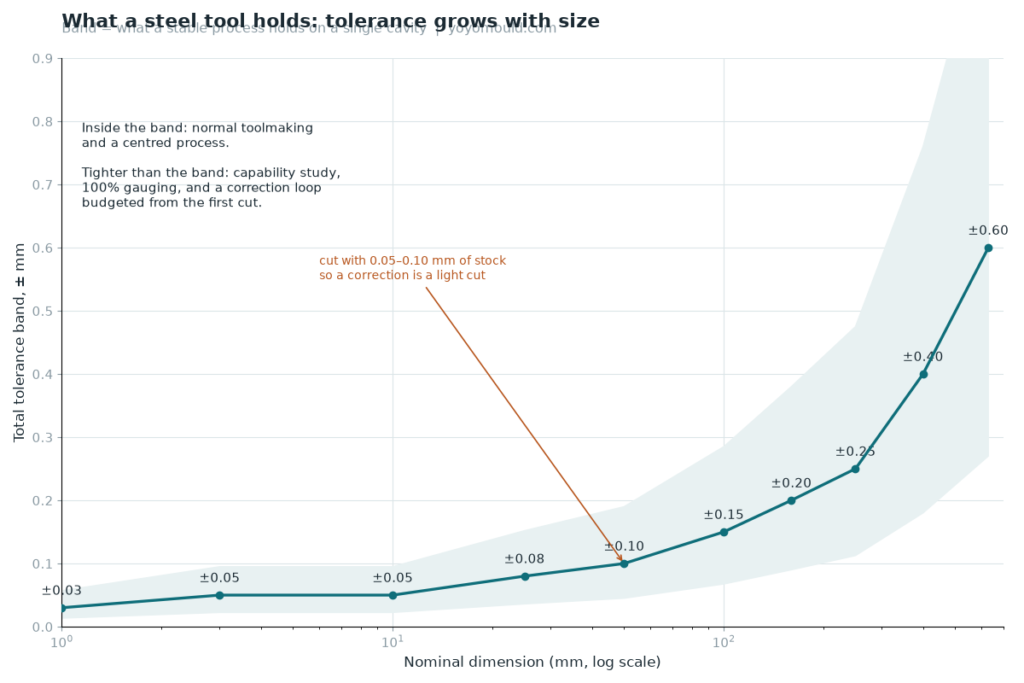
A tolerance of ±0.02 mm on a 200 mm dimension is not a tolerance, it is a wish. Toolroom accuracy is not the limit — the limit is that the process varies, the steel wears, and the measurement itself has an uncertainty. The band below is what a stable single-cavity process in an engineering resin holds without heroics.
| Nominal dimension | Practical band (±) | Comment |
|---|---|---|
| up to 10 mm | 0.03–0.05 mm | Gauge choice starts to matter |
| 10–50 mm | 0.05–0.10 mm | Normal toolroom work |
| 50–120 mm | 0.10–0.15 mm | Watch differential shrink |
| 120–250 mm | 0.15–0.25 mm | Datum scheme must be agreed |
| 250–500 mm | 0.25–0.40 mm | Flatness usually binds before size |
| over 500 mm | 0.5–0.6 % of size | Warp governs, not shrink |
Tighter than the band is possible — handheld and connector work lives there — but it is bought with a capability study, 100 % gauging, a settled process window and a correction budget. The question to ask is not “can you hold ±0.03 mm”, it is “which dimensions need it, and what happens at T1 if they miss”. A part with three critical dimensions and thirty loose ones is a different job from a part with thirty-three tight ones.
Leave stock where a correction is likely
Steel can be removed in a controlled way; putting it back means welding, inserts or a new block, and every one of those is a decision with a schedule attached. So the practical rule on any dimension that is both critical and uncertain — a seal groove, a shut-off, a mating height — is to cut it with 0.05–0.10 mm of stock left on the wall. If the first samples come out undersized, opening the cavity is a light cut. If they come out oversized, the tool is already at nominal and the correction is easy to plan.
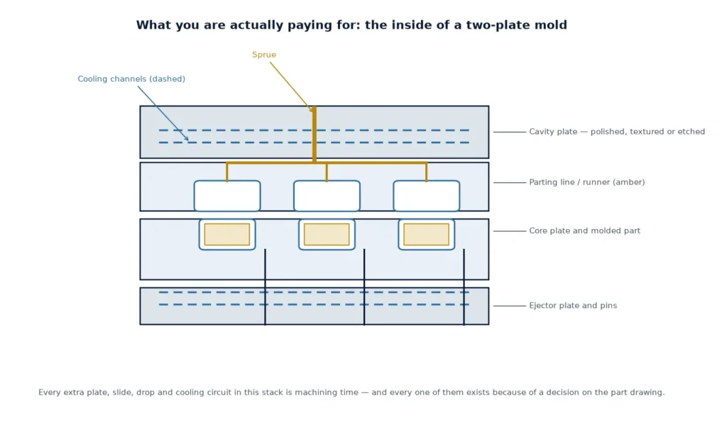
This is also why the surface finish and the parting line deserve a moment’s thought before cutting. A dimension that has to be adjusted sits on a steel face that will be re-polished afterwards, and a face with an EDM recast layer or a deep texture is expensive to adjust cleanly. The DFM review before cutting steel is where these decisions are cheap; after heat treatment only the schedule is flexible.
Where the tolerance is actually lost
Most dimensional arguments at T1 are not about the shrink figure. They are about the stack underneath it: cavity-to-core alignment (0.02–0.05 mm on a good tool, more on a worn one), plate flatness, ejector and slide clearances, gate freeze variation between cavities, and the measurement itself — a part measured warm on the press reads differently from the same part measured at 23 °C the next morning. Polyamide that has not been conditioned is a moving target for a week.
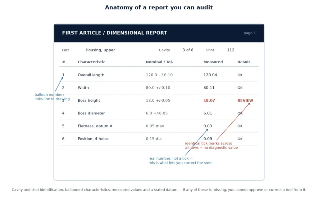
Multi-cavity tools add cavity-to-cavity variation on top of all of it, because the fill and packing balance is never perfect. If the drawing allows one band for all cavities, the band has to be wide enough for the worst cavity, not the best. Agreeing the datum scheme and the gauging method before the first cut costs an hour and prevents the classic exchange where two labs disagree and nobody can tell whether the tool or the measurement is wrong.
The correction loop, planned in advance
Assume there will be a correction and make it small. That means: measure after stabilisation, not straight off the machine; separate dimensions that missed because of shrink from those that missed because of steel; correct the steel only after the process has been centred, because a hot mould and a cold mould give two different answers and neither is the tool’s fault. Correction rounds cost time when they are discovered late and cost almost nothing when they are the expected next step.
For parts where flatness or a mating interface is the real requirement, it is worth checking the cooling layout before blaming shrink: an unbalanced circuit produces a temperature difference across the part, and a temperature difference produces differential shrink, and differential shrink produces a part that is dimensionally correct and still will not sit flat. Cooling circuit design and tolerance are the same conversation viewed from two ends.
A short checklist before the drawing is released
- Resin fixed, with the supplier’s shrink range and the wall thickness it was measured at.
- Gate position decided, because it sets the flow direction and therefore the anisotropy.
- Critical dimensions listed separately from cosmetic and non-functional ones.
- Each critical dimension marked: cut at nominal, or cut with stock for correction.
- Datum scheme and gauging method written on the drawing, not agreed verbally later.
- Measurement condition stated: stabilisation time, temperature, and conditioning for PA.
- Cavity-to-cavity band agreed for multi-cavity tools.
- T1 correction round expected and budgeted, not treated as a failure.
None of this replaces a mould flow study on a difficult part, and none of it is a substitute for measuring the first samples properly. What it does is make the first cut a good guess instead of a gamble — and on a tool where the steel has already been hardened, a good guess is the whole difference between one correction and three.
Frequently asked questions
Is 2 % the right shrink allowance for polypropylene?
For a wall around 2 mm, yes — 1.5–2 % is the usual middle. For a 4 mm wall, 2 % will come out undersized because thick sections shrink more, and a thin 1 mm wall may come out oversized. The datasheet range is measured on a standard test plaque, not on your part, so the wall and the gate position have to be applied on top of it.
Can a mould be made to ±0.02 mm?
The steel can be machined and measured to that. The moulded part cannot be guaranteed to it across a production run without a capability study, a controlled process window and 100 % gauging. What is realistic is a few critical features held tight while the rest of the part sits in a wider band, and that mix should be written on the drawing.
Why does the same part measure differently on two machines?
Because shrink follows the process, and the process follows the machine: shot size, check ring condition, screw diameter, hold pressure profile and mould temperature control all shift the packing history. If the dimensions only pass on one machine, the tool has no process window — it has a coincidence. The fix is usually a slightly wider gate or a packing change, not a steel correction.
How long should parts stabilise before measuring?
For amorphous resins, 24 hours at 23 °C is normally enough. For polyamide, moisture uptake continues for days, so either measure dry and condition afterwards or agree a conditioned state and measure there. Measuring straight off the press and deciding a steel correction from that number is the most common way to make a good tool worse.
What is the difference between mould shrink and post-mould shrink?
Mould shrink is the change between cavity and part at ejection plus a short settling period. Post-mould shrink is what continues afterwards as residual stress relaxes and, in polyamide, as moisture is absorbed — which grows the part rather than shrinking it. The allowance on the drawing has to account for the second one whenever the part will be measured in service rather than on the bench.
Have a drawing with tolerances you are not sure the tool can hold?
Send the part drawing, the resin and the dimensions that are actually functional. We will come back with the allowance we would cut to, the dimensions we would leave stock on, and the band we expect to hold.