Mold structure · one stack, five consequences
Two-Plate or Three-Plate Mold: Choosing the Structure Before the Gate
Before gate position, cooling or ejection can be settled, someone has to choose the plate stack. Two-plate, three-plate or hot runner decides where the gate is allowed to land, how the runner comes out, how tall the tool stands, and whether it fits the press it was bought for.
Most of the cost of a mold is decided in a week of drawing, and the first drawing decision is not the gate, the cooling or the ejector: it is the plate stack. A two-plate tool opens on one plane and every gate has to be reachable from the outside. A three-plate tool opens on two planes so the runner can be pulled away from the top of the part, which puts a gate almost anywhere on the projected area. A hot runner removes the runner altogether and moves the cost to a manifold. Everything else in the tool follows from that choice.
What the plate stack decides at once
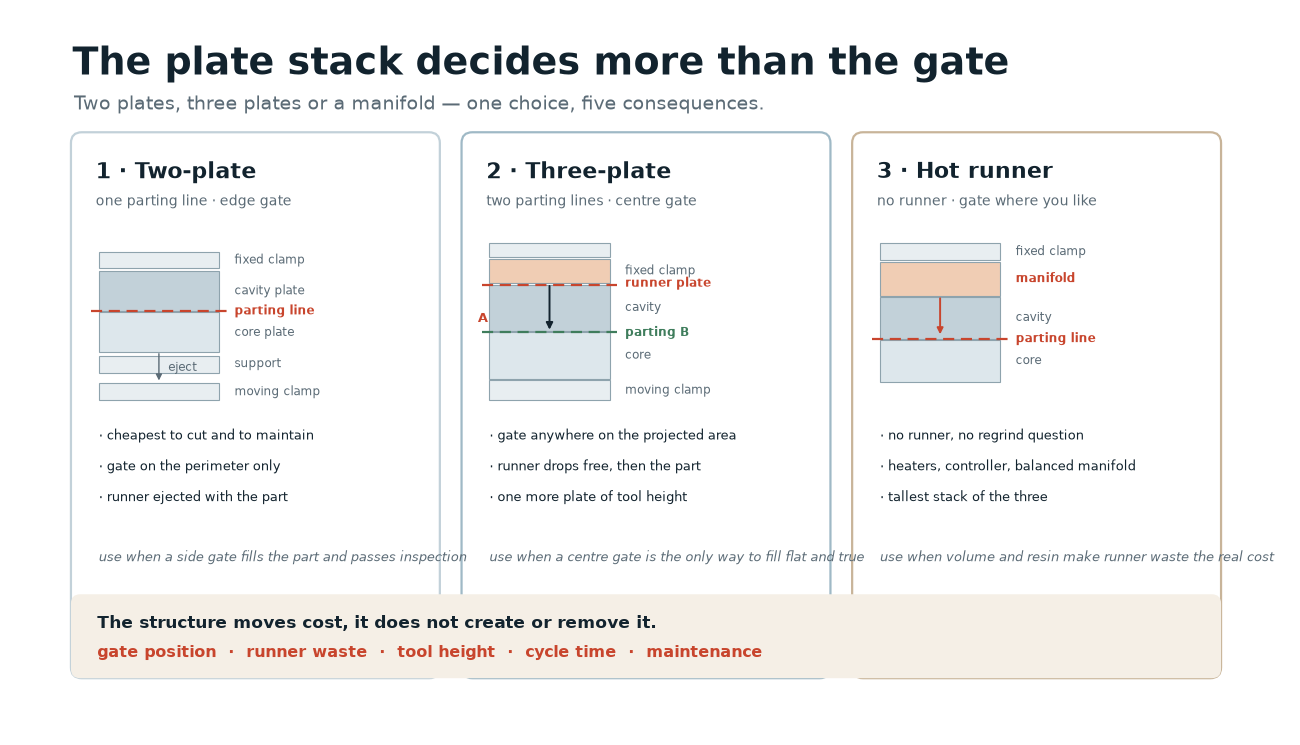
First, where the gate can land, and therefore where the weld lines and the gate mark appear. Second, how much material is injected and then thrown away as runner per shot, because a cold runner is part of the shot whether or not it becomes a part. Third, how tall the closed tool stands, because tool height plus opening stroke has to fit inside the machine’s daylight. Fourth, how much mechanism moves on every cycle, which is where maintenance cost lives. Fifth, how the part is ejected, because the runner has to leave the tool as well as the part.
Two-plate: one parting line, gate from the side
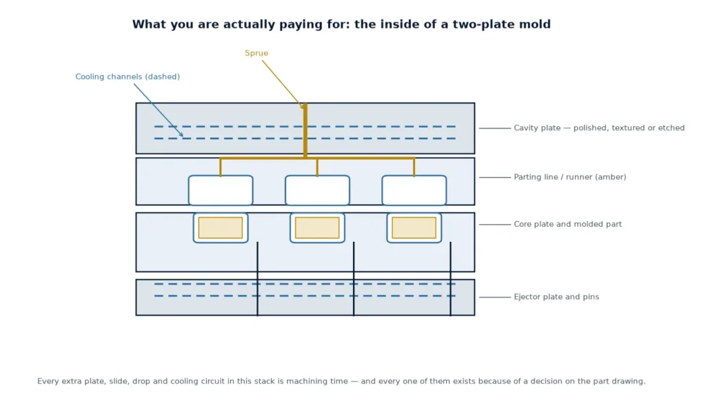
A two-plate mold is a cavity plate and a core plate that close on a single parting line, with the runner cut into that same plane and the sprue entering through the fixed half. It is the simplest mechanism a mold can have: one opening movement, one ejection movement, no sequencing. The gate sits on the edge of the part, on the parting line, and the runner is ejected together with the part and trimmed afterwards.
The limitation is purely geometric. A gate can only reach the perimeter of the projected area, so a large flat cover gets fed from one edge and the flow front travels the whole width before the cavity fills. That shows up as a pressure gradient across the part, higher clamp force than the part deserves, and a predictable tendency to warp away from the gate. None of that is a defect of the structure; it is the structure doing what it is supposed to do, and being asked for something it cannot give.
Three-plate: two parting lines, gate anywhere
A three-plate mold adds a runner plate between the fixed clamp plate and the cavity plate, so the tool has two opening planes. The first opening separates the runner plate from the cavity plate and pulls the sprue; the runner drops free, and the second opening releases the part. Because the runner now ends above the cavity rather than at its edge, the gate can be placed at any point of the projected area — including the centre of a large flat part, or the centre of each cavity in a multi-cavity layout.
That single change answers several problems at once: a centre gate fills a flat part symmetrically instead of from one side, which reduces the pressure gradient and gives a much better chance of a flat part; small cavities can be laid out symmetrically around a central sprue with equal flow lengths; and the gate mark moves from a visible side wall to a face that is often hidden inside an assembly. It is the standard answer for thin-walled covers, housings and any part where the customer will photograph the outside.
Opening sequence is a mechanism, not a plate change
The price of that gate freedom is a sequence. The tool has to open the runner plane first, hold the cavity plate back on a positive stop or a latch, wait for the runner to drop, and only then open the main parting line and eject. That sequence is created by puller bolts, limit switches, springs, latches and stripper components, and every one of those parts moves on every cycle. When a three-plate mold misbehaves, the symptom is usually in the sequence rather than in the cavity: a runner that stays hanging, a sprue that tears, a plate that opens in the wrong order, a puller bolt that has stretched. That mechanism is also why a three-plate tool needs a longer opening stroke than the part height suggests.
| Structure | Gate position | Runner waste | Tool height | Extra mechanism | Best fit |
|---|---|---|---|---|---|
| Two-plate | perimeter only | full runner, every shot | lowest | none | single-cavity, side gate acceptable |
| Three-plate | any point of projected area | full runner, every shot | higher by one plate | latch, pullers, runner ejection | centre gate, multi-cavity, cosmetic faces |
| Hot runner | any point, no runner | none | higher, plus manifold | manifold, heaters, controllers | large volume, thin wall, engineering resins |
Tool height against machine daylight
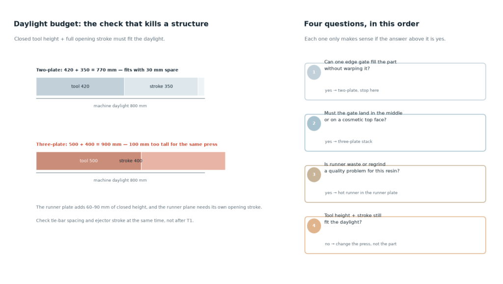
A three-plate stack is taller than the two-plate version of the same part, typically by the depth of the runner plate, and the opening stroke is longer because the runner plane has to open first. Both numbers are fixed before the steel is ordered and both can make a tool that does not fit. The check is mechanical: closed tool height plus the full opening stroke must be less than the machine’s maximum daylight, and the tool has to pass between the tie bars, with enough ejector stroke and enough room behind the moving platen. A part that needs 90 mm of stroke for its own height can need 150 mm once the runner plane is included.
This is also where a structure decision quietly becomes a press decision. Buying a taller tool for a press that only just fits the part is a common way to discover, at T1, that the mold has to be redesigned or the job moved. Tonnage is the other half of the same conversation, and it is calculated from projected area and cavity pressure rather than from tool size — see clamping force and tonnage for the arithmetic.
Material decides some of it for you
A cold runner is not free material, it is material that has been through the barrel and will go through it again if it is reground. Resins with a narrow processing window — PC, POM, PA, and anything glass filled — lose molecular weight and impact strength with each pass, so the allowed regrind percentage is limited and the runner becomes scrap with a price. PVC is heat sensitive enough that a cold runner with a long dwell is a quality risk in itself. Transparent parts and colour changes make the runner a contamination problem rather than a recycling one. In those cases the runner waste, not the tool cost, is what decides between a three-plate cold runner and a hot runner.
The trade is genuine in both directions: a hot runner removes the runner and the regrind question, but adds heaters, thermocouples, a controller, a manifold that has to be balanced, and a new class of failure — a heater that dies mid-run. The comparison of feed systems is covered in hot runner versus cold runner.
When two-plate is simply the right answer
Two-plate wins more often than its reputation suggests. A single-cavity tool for a large, thick-walled part with an acceptable edge gate has nothing to gain from a runner plate: the flow length is short, the part is heavy enough that the runner is a small fraction of the shot, and the mechanism that three-plate adds would only be one more thing to maintain. Prototype and bridge tooling, parts in heat-sensitive resin, and jobs where the part will be machined or painted after molding all sit comfortably on a two-plate stack. The decision is wrong only when a centre gate was actually needed and the side gate was chosen to keep the tool simple.
When three-plate earns its mechanism
Three-plate pays when the gate position matters more than the mechanism: a large flat face that has to fill evenly, several small cavities that need equal flow lengths, a visible top surface that cannot carry a side gate mark, or a part whose warpage is dominated by an asymmetric fill. It is also the usual structure when a cold runner is required for material reasons but the gate still has to be central. In those cases the runner plate is doing real work, and the latch and puller hardware is the cost of getting the gate where the part needs it.
What to settle before the plate stack is fixed
- Which faces are cosmetic, and whether a gate mark is allowed on any of them.
- Whether the part can be fed from one edge without unacceptable warpage or pressure loss.
- The machine the tool is going on: daylight, tie-bar spacing, ejector stroke, shot size.
- Cavity count and layout, and whether flow lengths will be equal.
- Resin and regrind policy — this decides whether runner waste is scrap or acceptable.
- Whether the runner has to be removed automatically or can be trimmed offline.
Get those six answered and the structure chooses itself; skip them and the same conversation happens later, with steel already cut. The gate layout that follows is covered in gate types and gate location, the ejector side in ejection system design, and cavity layout in how many cavities.
Frequently asked questions
What is the difference between a two-plate and a three-plate mold?
A two-plate mold has one parting line: the runner is cut into the same plane and the gate has to sit on the edge of the part. A three-plate mold has a runner plate between the fixed half and the cavity plate, so it opens on two planes; the runner is pulled away from the top of the part and the gate can be placed anywhere on the projected area.
Is a three-plate mold more expensive than a two-plate mold?
Yes, for the same part: one more plate, two more opening planes to fit, a latch or positive stop sequence, puller bolts and runner ejection. Whether that difference is worth paying depends entirely on whether a centre gate is needed — if a side gate would fill the part and pass inspection, the runner plate is money spent on a mechanism that solves nothing.
Does a three-plate mold take longer to cycle?
Usually slightly longer. The tool has to open the runner plane, hold, let the runner drop, then open the main parting line and eject, and the runner is an extra mass that has to cool enough to be pulled without tearing. The penalty is often in the runner cooling time rather than the mechanical movement, and it can be reduced by thinning the runner where the process allows.
Why does the runner keep hanging in my three-plate mold?
Most often the runner is too thick to cool in the time the cycle allows, or the sprue pull is not centred, or the latch that should hold the cavity plate back has worn so the plates open in the wrong order. It is a sequence and cooling problem far more often than a plate geometry problem. Check the puller bolt stretch and the positive stop before changing the runner.
Can a three-plate mold use a hot runner?
Yes. A hot nozzle can be fitted into the runner plate so the gate lands centrally with no cold runner at all, which removes the runner drop and the regrind question while keeping the centre gate. The tool then needs a manifold, heaters and a controller, and the opening sequence is simpler than a cold-runner three-plate stack.
How do I know whether the mold will fit my press?
Closed tool height plus the full opening stroke must fit inside the machine’s maximum daylight, the tool must pass between the tie bars, and the ejector stroke plus ejector plate thickness must fit behind the moving platen. A three-plate stack adds a runner plate to the closed height and needs a longer stroke, so check with the actual plate stack, not with the part height.
Not sure which structure your part needs?
Send the part model, the resin and the press you intend to run it on. We will say whether a two-plate stack can fill it, what a centre gate would change, and whether the tool fits the machine before the plate stack is drawn.