Tooling validation
Injection Mold Trials: What T0, T1 and PPAP Sampling Actually Require
Most tooling arguments are not about the mold — they are about what a sample was supposed to prove. Here is how the three trial gates differ, what evidence belongs in each one, and the four records worth asking for before you agree that a tool is finished.
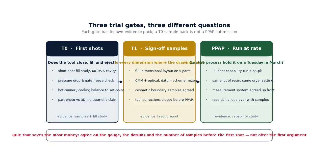
A trial is a measurement event, not a photo opportunity. The confusion starts because three very different questions get asked under the same word — “trial” — and the same five parts get photographed for all three. T0 asks whether the tool works. T1 asks whether the part matches the drawing. PPAP asks whether the process can keep matching it next month, on a different shift, with a different lot of resin. Those questions need different samples, different instruments and different people in the room.
Why the gates get blurred
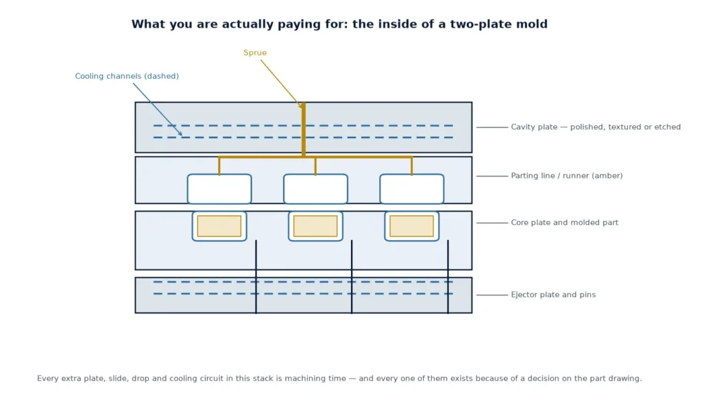
On a simple two-plate tool with one cavity, the three gates often collapse into a single afternoon and nobody notices the difference. On a multi-cavity tool with sliders, a hot runner and a textured surface, they cannot. A cavity that fills completely at T0 can still be 0.08 mm out at T1 once the tool reaches steady temperature, and a part that is dead-on at T1 can drift out of tolerance after eight hours of running because a core is cooling unevenly.
The practical consequence: sampling plans written after the first argument tend to be written by whoever is louder. Agreeing the plan before steel is cut is cheaper, and it is the part of trial planning that shows up directly in the cost of a tool — re-cutting a pocket because the datum scheme was never fixed is the most expensive sentence in this article.
T0 — does the tool close, fill and eject?
T0 is a tooling event, not a part event. The output is a fill study and a list of mechanical problems, not a dimensional verdict. What we want to see coming out of T0:
- A short-shot series across the cavity, typically filling 60–95% of the volume, so the flow front can be read and weld-line positions confirmed
- Gate freeze and pressure-drop behaviour at the intended hold pressure, not at whatever pressure happened to make a complete part
- Hot-runner and cooling circuits holding set-point, with manifold and cavity temperatures logged rather than assumed
- Ejection, slider travel and lifters moving without witness marks, and any interference corrected in the tool rather than compensated in the process
- A first-article photo set next to the 3D model, marked as “T0, cosmetic not yet agreed”
Two rules keep T0 honest. First, do not accept a dimensional report at T0 as a sign-off; the tool is still changing temperature and the process window is not defined. Second, write down every change made during T0, even the ones that feel trivial — a gate opened by 0.2 mm at T0 is a changed variable for every measurement that follows.
T1 — is every dimension where the drawing says?
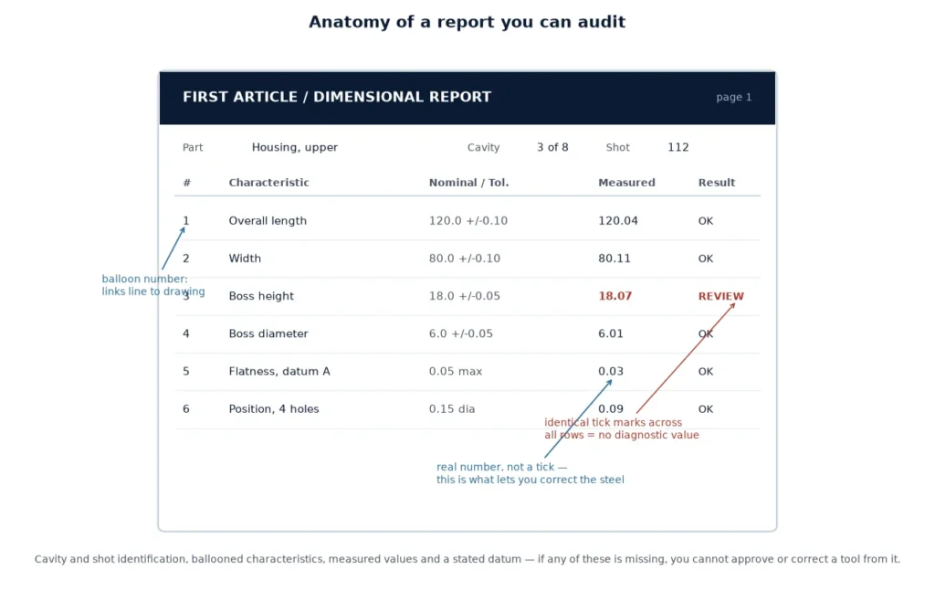
T1 is the dimensional gate, and it is where the datum scheme has to be final. We measure a layout on five parts from a settled process, on the instruments named in the plan, and report against the drawing rather than against a shop-floor convenience. Anything that cannot be measured repeatably needs a functional gauge agreed in advance — arguing about a 0.03 mm position tolerance with a caliper at the end of the table is not a measurement, it is a negotiation.
| Feature type | Typical instrument | What the report must state |
|---|---|---|
| Cavity / core dimensions | CMM, temperature-compensated | Datum scheme, probe diameter, part temperature at measurement |
| Position and profile | Optical / vision | Alignment method, reported as true position |
| Flatness, warpage | Surface plate + indicator, or scan | Free state or restrained, and the clamping condition used |
| Threads, inserts | Go / no-go gauges | Gauge ID and calibration date |
| Cosmetic surface | Boundary samples, agreed photos | Lighting, viewing distance, texture reference (e.g. SPI/VDI grade) |
Cosmetic acceptance deserves its own line because it is the least quantitative and the most argued. Two people looking at the same sink mark from different angles and distances will disagree forever. Boundary samples — one part that is acceptable, one that is not, both signed and dated — turn an opinion into a reference. It costs one meeting and it removes a category of dispute permanently.
If the plan calls for texture, the trial sequence matters: etch the cavity, then re-run the cosmetic boundary samples, because a textured surface hides flow lines in some areas and exaggerates them in others. For steel and surface-treatment decisions behind this step, there is a separate note on P20, 718H, S136 and NAK80 worth reading before the cavity is finished.
PPAP — can the process hold it?
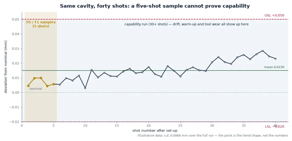
The third gate is the one that gets skipped when a project is late. Capability is a statement about a distribution, so it needs a run long enough to contain the distribution: typically thirty consecutive shots on one cavity, taken after the tool and the machine have reached steady state, from one lot of resin dried the same way it will be dried in production. From those parts you can compute a mean and a standard deviation, and only then say something about Cp and Cpk.
Two details make the difference between a capability study and a ritual. First, the measurement system has to be understood before the study — a gauge that repeats to ±0.02 mm cannot resolve a 0.03 mm tolerance, no matter how many parts you run. Second, the study has to be run on the machine and with the settings that production will actually use. A capability figure generated on a development press with a hand-set profile is a number about that afternoon, not about the tool.
Where capability comes out marginal on a feature that cannot be changed — usually a warpage or shrinkage case — the honest options are to change the part tolerance, change the process window, or change the tool. All three cost something. What does not work is averaging a marginal feature across good ones and calling the tool approved; that is how a tool arrives at a customer site already arguing with itself.
The four records worth asking for
Whatever the gate, the same four documents do most of the work of keeping a project out of dispute:
- The sampling plan — which features, which instruments, how many parts, agreed before the first shot
- The change log — every tool correction with a date, so a later measurement can be attributed to a known state
- The measurement report — drawing reference, datum scheme, actual values, instrument and part temperature
- The capability study — raw readings, not only the computed indices, so the calculation can be checked
Ask for them as a set. A measurement report without the sampling plan is unverifiable; a capability study without raw readings is a claim. On smaller tools a single page can carry all four, and that page is the difference between a tool that is finished and a tool that is merely shipped.
Where trial plans usually break
Three failures repeat often enough to be worth naming. The first is measuring too early: parts taken before the mold reaches thermal steady state describe a tool that will not exist in production. The second is measuring with the wrong instrument: a tolerance tighter than the gauge resolution is already a decision that nobody made. The third, and the expensive one, is treating T0 acceptance as project acceptance — the sample package gets filed, the capability run never happens, and the first real signal of trouble arrives as a rejected shipment.
The fix is not more paperwork. It is deciding, in writing and before the first shot, which gate is allowed to answer which question. For the tooling side of that decision — how the tool is built and what the different mold types imply for trial complexity — see the design and engineering notes on plastic injection molding and mold design and engineering. Cooling layout, which drives a large share of trial drift, is covered in cooling circuit design and cycle time.
Frequently asked questions
What is the difference between T0 and T1?
T0 is a tooling event: does the tool fill, eject and hold temperature. T1 is a dimensional event: does every feature match the drawing on a settled process, measured with the agreed instruments. T0 samples are usually not signed off dimensionally; T1 samples are.
How many samples do I need for PPAP?
Enough to describe a distribution — commonly thirty consecutive shots per cavity after the process reaches steady state, from one resin lot. Five parts will tell you the tool works; they cannot tell you whether the process holds the tolerance.
Can a tool be approved if one feature is out of tolerance?
Only as a documented deviation with a date and an owner. Averaging a marginal feature across good ones hides exactly the risk a capability study exists to find. The options are to change the tolerance, the process window, or the tool.
Who should be present at T1?
Whoever owns the drawing, whoever will measure the parts in production, and whoever can approve a deviation on the spot. A trial where the customer’s quality engineer is absent tends to become a second trial.
Does a textured surface change the trial plan?
Yes. Etching changes flow behaviour and hides some defects while exaggerating others, so cosmetic boundary samples should be taken after texturing, not before, and the dimensional report should be from the same state of the tool.
Planning a trial before the steel is cut
Send the part drawing and the intended resin and we will say which features are likely to need a capability run, and what the sampling plan should contain.