
Comprehensive Mold Solutions

Mold Design & Engineering

DFM analysis, mold flow, tool design and trial validation — the engineering work that decides whether a tool earns its money.

Most tool problems are designed in, not built in

Warpage, short shots, sink marks, long cycles and ejection damage are usually visible in the design review long before they appear on the press. That is why we insist on a DFM report before any steel is ordered.

The report is written in plain language, with a suggested change and the consequence of not making it, so the decision stays with you.

  • DFM report on draft, wall thickness, ribs, bosses and gates
  • Mold flow analysis for fill, packing, cooling and warpage
  • Full 2D/3D tool design with hot runner and standard component selection
  • Trial validation with dimensional layout and process window
Professional engineering team discussing product prototypes and DFM analysis, ensuring seamless communication

What the engineering package includes

Design for manufacture analysis of a plastic part

DFM analysis

Practical comments on geometry, tolerances, draft and material choice, with a risk rating for each item.
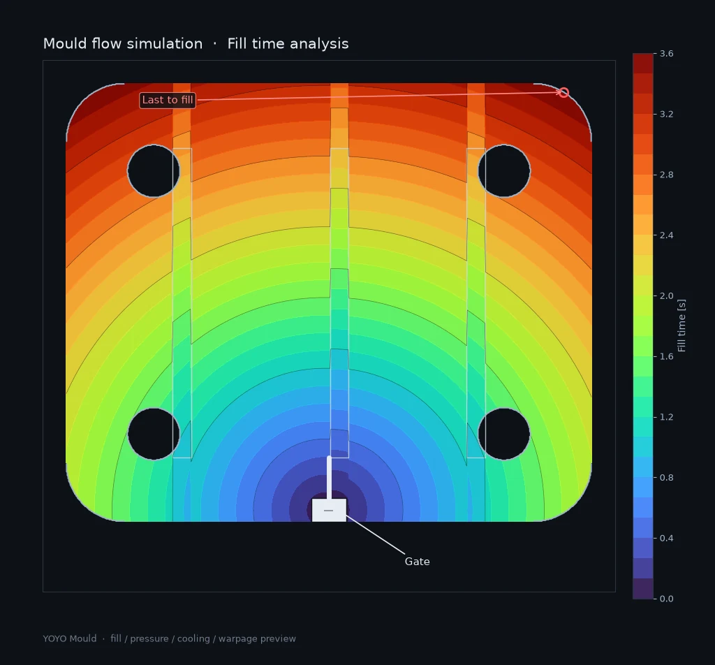
Mold flow simulation showing fill time analysis of a plastic part

Mold flow simulation

Fill, pressure, temperature, cooling and warpage prediction for critical parts.
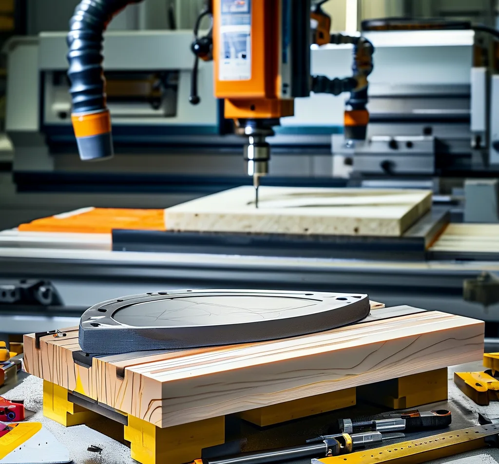
Tool design and manufacturing shop

Tool design

Complete tool drawings including cooling circuits, ejection, slides, lifters and hot runner layout.
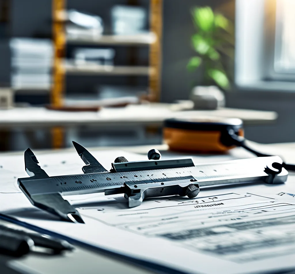
Dimensional validation of a trial shot part

Trial validation

T1 and T2 trials with sample reports, dimensional layout and a documented process window.

Deliverables per stage

StageWhat you receive
Design reviewDFM report with suggested changes, risk rating and quoting assumptions
Mold flowFill, packing and cooling results for agreed critical regions
Tool design2D assembly and detail drawings, 3D model, bill of materials
TrialSamples, first article inspection report, dimensional layout, process sheet
HandoverTool record file, cooling and hydraulic schematics, spare parts list

The engineering sequence

01

Data intake

3D data, 2D drawing, material specification and annual volume.

02

DFM and quoting

Comments issued with the quotation, so cost and design risk are reviewed together.

03

Tool design and approval

Design review meeting, drawing approval, then release to machining.

04

Trial and correction

T1 samples measured; corrections planned and executed with a documented change list.

05

Validation and handover

Capability check on critical dimensions, tool record file and maintenance plan.

Frequently asked questions

Do I need to supply 3D data?

Ideally yes. Where only a sample part exists we can reverse-engineer the model, but the internal geometry is then an assumption and we will say so in writing.

Who owns the tool design?

You do. Tool drawings and 3D data are released to you, along with the tool record file at handover.

Can you work to our drawing standard?

Yes. We can issue drawings in your format and datum scheme, or in the DIN/ISO convention we use by default — whichever your quality system requires.

What happens if trial parts are out of tolerance?

Corrections are planned against the measured data, with the change list agreed before any steel is altered. Correction rounds are part of the tooling programme, not an extra purchase.

Send your part data for a free DFM review

We will send back comments, a risk list and a tooling quotation — usually within two working days.

Scroll to Top