EJECTION DESIGN
Ejection System Design: Pins, Sleeves, Strippers and Air
Most ejection problems are not ejection problems. They are draft, texture or shrinkage problems that show up as a white mark on the part. Here is how the four families are chosen, sized and laid out, and what to settle before the steel is cut.
Ejection is the last second of the cycle and the first place a customer looks when a part arrives with a mark on it. The system has to pull the part off the core against shrinkage grip, break the vacuum behind it, and do that on every shot for the life of the tool without leaving a witness. Four families cover almost every case: pins, sleeves, stripper plates and air. The choice is set by part geometry, not by habit, and the layout matters more than the count.
What the system is actually fighting
A part shrinks onto the core as it cools. For an unfilled commodity plastic the linear shrinkage sits roughly between 0.4% and 2%, and that number is the grip: a 100 mm deep core with 1.5% shrinkage holds the part with measurable interference along its whole length. Add the vacuum that forms between a flat core face and a flat part, add friction from texture, and add any undercut that has to slide, and the force needed to release the part can be several times what a first estimate suggests.
That force has to be delivered through the part itself. Everything about ejection design follows from that: contact area as large as the geometry allows, force as even as possible, and no single small area taking more load than the material can carry while warm.
The four families and where each one belongs
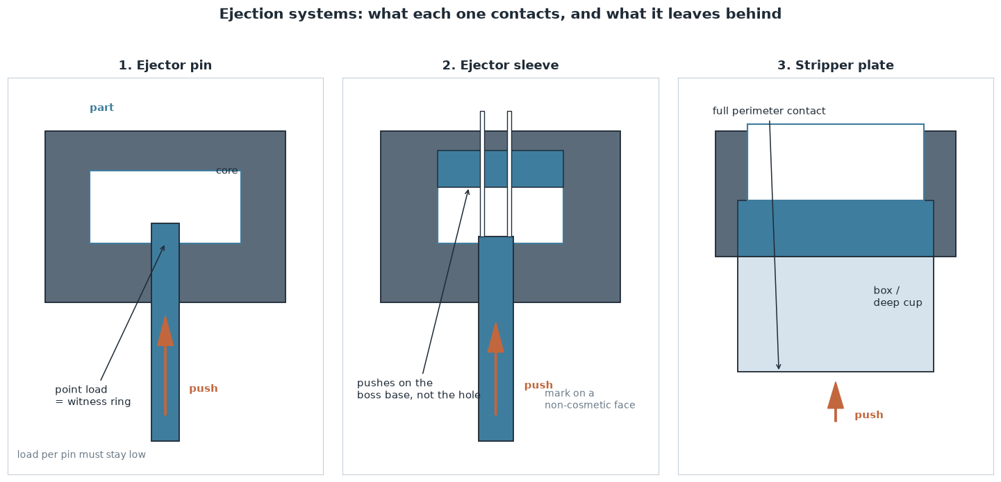
These are not interchangeable upgrades. Each one trades a different kind of freedom for a different kind of mark.
| System | Best for | Typical mark | Watch out for |
|---|---|---|---|
| Ejector pins | Flat or gently curved surfaces with room for a pad | Small circular witness, bright ring if over-loaded | Pins too small, too few, or landing on a cosmetic face |
| Sleeve (ejector sleeve) | Bosses and cylindrical pillars, especially screw bosses | Ring at the boss base, invisible if the sleeve is flush | Sleeve wall too thin, or clearance too tight and it galls |
| Stripper plate | Box shapes, deep thin-wall cups, parts with no room for pads | Full-perimeter line at the flange edge | Needs a straight release surface and a guided plate |
| Air / vacuum break | Large flat areas, thin walls, textured surfaces | No mechanical mark; a faint blush if air is late | Air must be timed before pins move, and vents must be clean |
A fifth family, lifters and sliders, is not really ejection: it releases undercuts before the part can be pushed. Those are covered separately in the undercut guide; the two systems have to be laid out together, because a lifter occupies the space where an ejector pin would otherwise sit.
Pin layout: balance beats count
The usual failure is not too few pins, it is pins in the wrong place. A layout that pulls one corner first tilts the part, and the tilt does two things at once: it loads the leading pins far beyond their share, and it drags the opposite wall against the core, which is where scuffing and white stress marks come from. The fix is to place pins around the projected centre of resistance, not around the geometric centre of the part, and to keep them symmetric about both axes wherever the geometry allows.
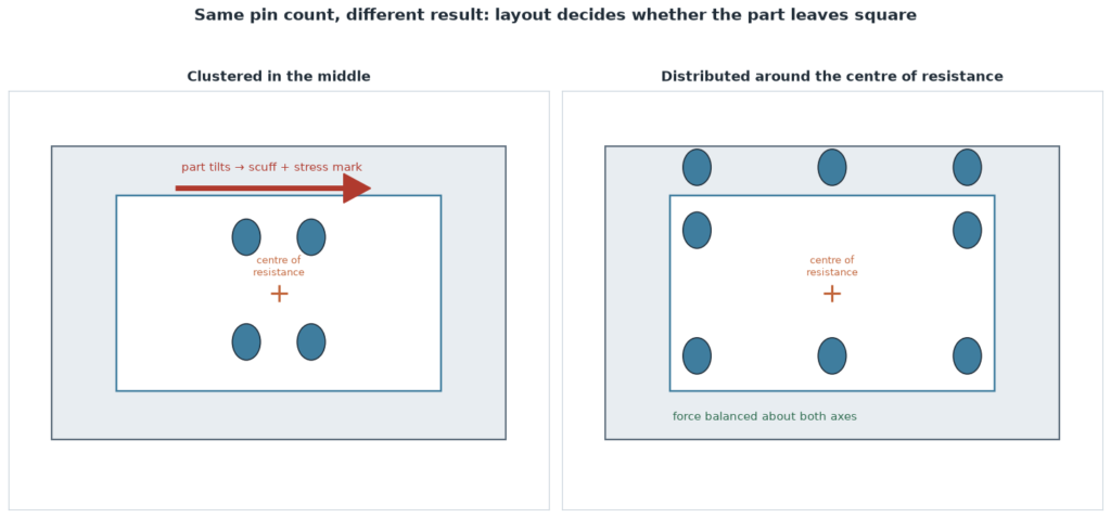
Three practical rules come out of that. Pins go under ribs, bosses, and the corners of deep draws, because those are the stiffest points and the ones that grip hardest. Pins avoid thin flat areas that will dish under load. And the part’s own stiffness is part of the design: a layout that works on a 2.5 mm wall can dish a 1.5 mm wall even when the force arithmetic says it is fine.
Sizing a pin: diameter, bearing length, buckling
A pin has to survive two separate loads. The first is compression: the force it carries divided by its cross-section, which for a hardened pin is rarely the limit. The second is buckling, and this is where small pins fail, because a long thin pin under load behaves like a column, and the critical load falls with the square of the free length. A pin that is comfortable at 60 mm of free length is not comfortable at 160 mm.
- Keep the unsupported length short: support the ejector plate, and step up to a larger pin shank behind the working diameter when the free length grows.
- Give the pin a shoulder or a headed seat so it cannot be pulled through the plate.
- Hardness and surface finish on the working end decide galling: a soft pin in a soft hole will seize long before it breaks.
- Vent the pin hole on the core side where a pin passes through a sealed face, otherwise the pin acts as a tiny hydraulic ram and the mark becomes a burn.
- Never load a pin on a sharp step or a thread start; move the pin 2–3 mm and the mark disappears.
Sleeves: the invisible answer for bosses
A boss with a screw hole in it is the classic case where pins cannot work. A pin on the boss top crushes the rim, a pin beside the boss bends the boss, and a pin inside the hole is not possible. A sleeve pushes on the annular face at the base of the boss, which is a large, flat, non-cosmetic surface, and the resulting mark sits on a face nobody inspects. Sleeve wall thickness deserves attention: too thin and the sleeve deforms or cracks, too thick and it eats the space the water line needs.
The clearance between sleeve and core pin is the second deciding factor. Tight enough to stop flash, loose enough not to gall when the tool is warm. If the boss sits on a slope, or the core pin is long and thin, the sleeve needs its own guidance rather than relying on the core pin to keep it straight.
Stripper plates: for boxes and deep cups
When the part is a box, a tub or a deep thin-wall cup, no arrangement of pins will push it without dimpling the base. A stripper plate contacts the whole rim at once, so the load per unit area is low and the part leaves square. The price is mechanical: the plate has to be guided on its own pillars, it needs enough stroke to clear the core, and the part needs a straight flange for the plate to land on. Where the flange is thin or the wall is tapered, the plate will bite and the part will tear at the corner.
Strippers also change the venting and the cooling layout, because the plate occupies the space where a conventional ejector box would sit. That is a decision to make at the layout stage, not after the plates are ordered.
Air: for flat, thin and textured parts
Air ejection breaks the vacuum and then floats the part off. It is the only system that leaves no mechanical mark, which makes it the right answer for large flat cosmetic panels, thin walls that cannot take a point load, and textured surfaces where any pin pad would be visible. The timing is what matters: air has to arrive before the part is pushed, not at the same instant, otherwise the pins still do the work and the air only adds noise. Air valves also need clean, dry supply and a vent path that does not clog with regrind dust or mould spray.
Draft angle and texture set the real pull force
The single most effective way to reduce ejection force is not a bigger ejector plate, it is more draft. A wall with 0.5° of draft will drag where the same wall with 2° releases. Texture multiplies the problem: a coarse grained or etched surface needs extra draft beyond the base angle, and the rougher the finish, the more the part grips as it cools. Deep ribs, sharp internal corners and glass-filled materials all push the required force up, and glass-filled grades also wear the sliding surfaces faster.
This is why ejection problems and shrinkage problems are often the same conversation. If the wall is thick in one place and thin in another, the part shrinks unevenly and grips unevenly, and no pin layout compensates for it. The shrinkage and tolerance guide and the DFM checklist both feed directly into the ejection layout, and cooling layout decides how much of the cycle the part spends shrinking onto the core in the first place.
The details that get forgotten
- Return pins and springs: the ejector plate must return before the mold closes, and the springs must be strong enough to do it with a cold, stiff tool.
- Early return and safety: if sliders or lifters move on the ejector motion, an early return switch or a mechanical interlock is not optional.
- Stroke check: the plate has to travel the full part depth plus clearance, and the machine’s ejector stroke has to be able to deliver it.
- Guided ejector plates: two guide pillars keep the plate square so pins do not bind when the tool is warm and the plates have grown.
- Ejector plate stop: a positive stop avoids over-travel crushing the part or the core.
- Service access: pins should be replaceable from the back of the tool without stripping the whole stack.
What to settle before cutting steel
Ejection is cheap to design and expensive to retrofit, because changing it usually means re-cutting the core, the plates and sometimes the base. Six items settle it: which surface may carry a mark; where the part grips hardest; whether the part has the stiffness to be pushed in one plane; which family the geometry allows; how the stroke is delivered; and how the chosen system interacts with cooling, venting and any lifter. Getting those six answered at the drawing stage is what keeps the first shot looking like the last one.
Where ejection sits in the tooling conversation
When a part is quoted, the ejection decision is one of the things that separates a tool that runs quietly for years from one that needs its pins replaced every quarter. It is worth settling with the molder before the design is frozen rather than after the first trial, when the only remaining option is to work around it. If you want a second opinion on a layout, send the part drawing and we will review the release side alongside the rest of the tool design.
Frequently asked questions
How many ejector pins does a mold need?
There is no fixed number. What matters is that the pin area is large enough that the pressure on the warm plastic stays low, and that the pins sit under stiff features and around the centre of resistance. A small part may need four pins; a large flat panel may need twenty plus air. Counting pins before deciding where they go is the usual mistake.
Can ejector pins leave marks on a visible surface?
They will leave something. A well-sized pin leaves a faint, even witness that polishing can reduce but not remove. If a face must be untouched, the answer is to move the ejection to a non-cosmetic face, or to use a stripper plate or air so the load is spread or absent.
When should a stripper plate be used instead of pins?
When the part is a box, a deep cup or a thin-wall container that would dimple under point loads, and when the geometry offers a straight rim for the plate to land on. If there is no continuous flange, a stripper plate tends to bite and tear instead of release.
Does more draft reduce ejection force?
Substantially. Draft turns sliding friction into a much smaller resistance, and it does so without adding any hardware. Texture, deep ribs and glass-filled materials all raise the force needed, and each of them needs extra draft on top of the base angle to release cleanly.
Why do parts stick even with plenty of pins?
Usually vacuum on a flat core face, uneven shrinkage from uneven wall thickness or cooling, or an undercut that was never released. Adding pins to a sticking part treats the symptom; the cause is normally in the cooling layout, the wall section or the release geometry.
Can air ejection be added to an existing mold?
Sometimes, if the core has room for the valve seat and a safe air path, and if the machine or the tool can sequence air ahead of the ejector motion. It is a layout decision as much as a hardware one, which is why it is better settled before the core is cut.
Have a part that is hard to release?
Send the drawing or the 3D file and we will look at the release side together with the rest of the tool design: draft, shrinkage, the surfaces that may carry a mark, and the ejection system that fits them.