Insert molding · metal to plastic
Insert Molding Design Rules: Metal Inserts, Bosses and Pull-Out Strength
A threaded insert that spins or pulls out is a geometry problem, not a molding problem. Here is what actually holds an insert, how thick the boss has to be, and where the melt has to flow.
Insert molding puts a machined metal part into the tool and molds plastic around it, so the finished component arrives with its thread, its bearing surface or its electrical contact already in place. The design question is never “can we mold around it” — almost anything can be molded around once. The question is whether the plastic will still be gripping that insert after a thousand cycles of torque, a thermal cycle from −20 °C to 90 °C, and a drop test. Retention comes from interlocking geometry: knurls, grooves, flats, a flange, or a hole the melt flows through. A smooth pin in a smooth boss is held by friction and shrinkage alone, and it will come out.
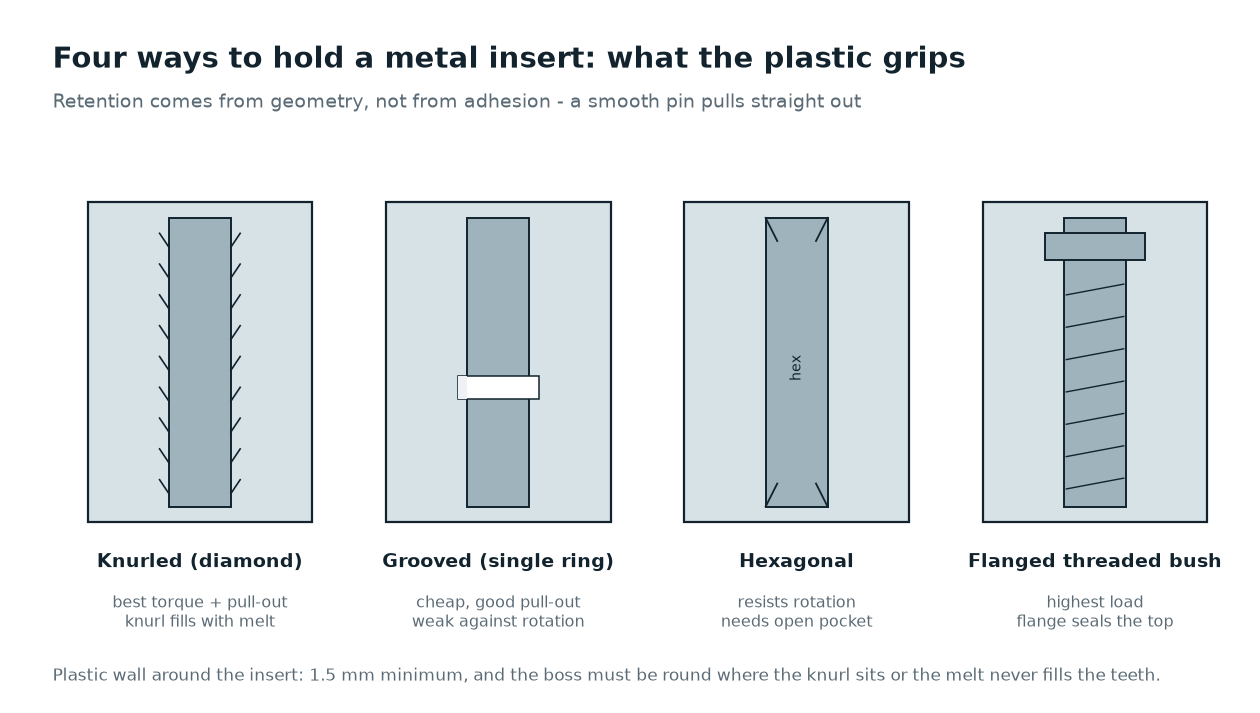
Four ways to hold an insert, and what each one is good for
Pick the interlock from the load the joint has to carry, not from what the insert supplier has in stock. Pull-out and torque are different loads and they need different features: a single groove resists pull-out well and rotation badly, a hexagonal body does the opposite.
| Insert geometry | Pull-out | Torque | Tooling note |
|---|---|---|---|
| Diamond knurl, full body | excellent | excellent | boss must be round and full at the knurl; melt must fill the teeth |
| Single circumferential groove | good | poor | cheapest option; add flats if torque matters |
| Hexagonal body | moderate | excellent | needs an open or split pocket; corners trap air |
| Flanged threaded bush | excellent | excellent | flange seals the top surface and sets depth |
| Through-hole with a shoulder | excellent | good | melt must be able to flow through the hole; watch knit line |
| Stamped and clinched plate | good | good | flat inserts need pin support against injection pressure |
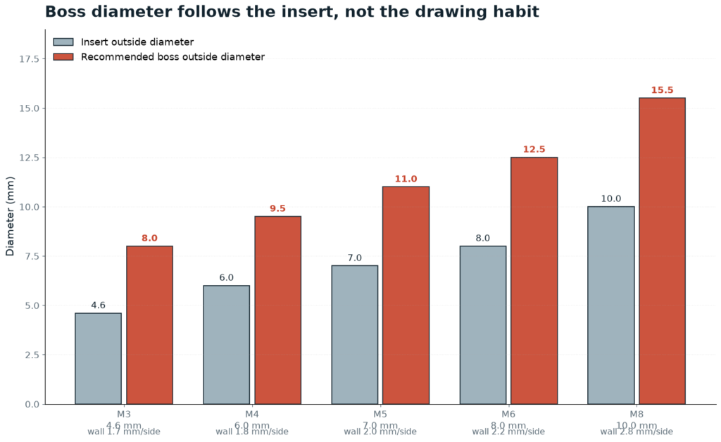
Boss diameter follows the insert, not the drawing habit
The plastic wall around an insert has to be thick enough to carry the hoop stress from shrinkage and thin enough that it does not sink on the visible face. The working minimum is 1.5 mm of wall on each side, and it goes up for a knurled insert because the melt must reach the bottom of every tooth. A rough envelope that holds up in practice: boss outside diameter is at least the insert diameter plus 3 mm, and for a knurled insert plus 4 mm.
Thermal expansion is what cracks the boss
Brass expands about twice as much as glass-filled PA66 or PBT per degree, and steel about a third as much as the plastic. When a hot part cools, the metal insert wants to stay large while the plastic wants to shrink onto it, and the boss is left in hoop tension. Add a thin wall, a sharp corner at the base of the boss and a resin that is notch-sensitive, and you get a crack that appears days after molding rather than at the press. Three habits keep it out of trouble: keep the wall at 1.5 mm or more with a fillet of at least 0.5 mm at the base, preheat inserts to 60–90 °C when the resin is a high-shrink engineering grade, and avoid placing an insert in a corner where three walls meet.
Where the melt has to go, and where the weld line lands
An insert is an obstacle in the flow path. The melt splits around it and rejoins on the downstream side, which puts a weld line exactly where the part is already weakened by the boss. Design rules that follow: gate so the weld line forms on a non-cosmetic face or behind the boss rather than across it; keep at least 1.5 mm between the insert and the gate so the metal does not chill the flow front; put a small overflow or a flow leader downstream of a large flat insert so the two fronts meet under pressure. On a flat stamped insert the melt also has to fill the thin gap under the plate — a 0.05 mm air gap is a short shot, not a clearance.
Tooling around the insert
Every insert needs a pin or a pocket that holds it during injection, because 500 bar of cavity pressure will move a 3 g brass bush. Pin the insert against the closing direction, not across it, and make the pin replaceable: an insert pin wears at the tip and a worn pin shows up as flash around the metal, which is a reject nobody catches until assembly. The pocket tolerance between insert and steel should be tight enough to prevent flash and loose enough to load by hand — a sliding fit with a 0.02–0.04 mm clearance per side is normal for a plated cavity. Venting matters more than usual here: the melt displacing air around a metal body will trap it, and an air trap against an insert is a short shot on the far side that looks like a bad insert. The rules for where to put those vents are the same as for any cavity — see mold venting design.
Molding the insert in, or putting it in afterwards
Every insert can be installed after molding, and sometimes that is the better decision. Molding in is stronger and it removes an assembly step, but it adds cycle time, exposes the tool to damage, and mixes two materials with different expansion in one shot. Post-mold installation — ultrasonic, heat staking, press-fit, self-tapping — keeps the tool simple and the cycle short, and it lets the insert be added after painting or plating.
| Method | Joint strength | Tool complexity | Use when |
|---|---|---|---|
| Molded in, knurled | highest | high, insert pins and loading | load path, sealing, part count matters |
| Molded in, plain boss then tap | moderate | low | prototype, low volume, thread rarely used |
| Ultrasonic installation | high | none, post-mold fixture | threaded boss in a thin housing |
| Heat staking | moderate | none | studs and light duty fastening |
| Press-fit with knurl | moderate | none | sheet-metal-like joints, low load |
The same interlock logic appears in two-material molding: our guide to two-shot and overmolding design constraints covers the plastic-to-plastic version of the same problem, where chemical bonding replaces mechanical grip.
How to inspect retention without guessing
Two tests settle most insert disputes, and both can be run at the trial. Pull-out: clamp the plastic, pull the insert axially at 5 mm/min, record peak load and the mode of failure — insert pulling out of the boss is a geometry problem, boss cracking is a wall-thickness or residual-stress problem, and the numbers point at different fixes. Torque: hold the part and apply torque until the insert spins, then cut a section through the boss and look at whether the knurl teeth are filled with plastic. Unfilled teeth mean the melt never reached the interlock, which is a gate or vent problem. Add a section check to the first-article report and the argument about “the insert felt loose” disappears.
What to put on the RFQ
- Insert part number, material and the retention features it already has.
- Load the joint must carry: axial pull-out and torque, with the direction.
- Resin, and whether the assembly sees thermal cycling, washing or sterilization.
- Whether the insert is supplied by the molder or free-issued, and how it is packaged.
- Which face must stay cosmetic, so the weld line can be planned away from it.
- Whether the threads are molded, cut after molding, or formed by the insert itself.
Most insert failures are decided on the print, long before the tool is cut. If you are designing a part around a thread or a bearing, send the insert drawing and the load case and we will check the boss geometry against the resin before the cavity is machined. The broader pre-cut review sequence is in our DFM checklist, and the numbers that govern how much the plastic moves around the insert are the same ones in shrinkage and dimensional tolerance.
Frequently asked questions
What is insert molding?
Insert molding is a single-shot process where a metal or ceramic part is placed in the cavity and plastic is molded around it, so the finished component includes the insert permanently. It differs from overmolding, where the second material is another plastic bonded to a molded substrate.
How thick should the plastic wall be around a metal insert?
At least 1.5 mm per side, and 2 mm or more for a knurled insert because the melt has to fill every tooth. As an envelope, the boss outside diameter should be the insert diameter plus at least 3 mm, or plus 4 mm for a knurled insert.
Why do inserts pull out or spin?
Almost always because the interlock is missing or was never filled. A smooth pin relies on friction only; a knurl whose teeth stayed empty because of a vent or gate problem behaves like a smooth pin. A single groove resists pull-out but not torque, which is why a spinning insert is usually a geometry choice rather than a molding fault.
Can brass inserts crack the plastic boss?
Yes. Brass expands roughly twice as much as a glass-filled engineering resin, so the boss sits in hoop tension after cooling. Thin walls, sharp corners at the boss base and notch-sensitive resins turn that into a crack days after molding. Fillets, adequate wall and preheated inserts reduce it.
Is it better to mold the insert in or install it afterwards?
Mold it in when the joint carries load, when part count matters, or when the insert has to seal. Install it afterwards when the tool should stay simple, when the cycle time matters, or when the part is painted or plated before assembly. Ultrasonic installation gives a strong joint without touching the tool design.
How do you test insert retention?
Two tests: an axial pull-out test at a controlled rate, which separates insert pull-out from boss cracking by the failure mode, and a torque-to-spin test followed by a section cut to see whether the interlock features are filled with plastic.
Check the boss before the cavity is machined
Send the insert drawing, the resin and the load the joint has to carry. We will check boss wall, interlock fill and weld-line position against the tool design.