DESIGN
Two-Shot and Overmolding: Design Constraints That Decide Whether the Tool Works
Most two-shot projects run into trouble on the part drawing, long before steel is cut. These are the constraints that have to be closed first, and how to check each one.
A two-shot part is buildable when four conditions hold at the same time. First, the second material has a defined surface to bond to — mechanical interlock or a known chemical affinity, not the assumption that elastomer sticks to plastic. Second, the interface can be closed by a shut-off that runs the full perimeter without a gap. Third, the elastomer wall is thick enough to fill and thin enough to freeze inside the cycle. Fourth, the tool’s second-half motion — rotate, retract or transfer — repeats to within a few hundredths of a millimetre for the life of the tool.
If one is missing, the project does not simply become difficult. It becomes a running cost: rejects at the shut-off, cycle time added to hide a short shot, repairs scheduled around a tool that was never given the geometry it needed. What follows is the order we check these constraints when a two-shot enquiry arrives.
What “two-shot” actually covers
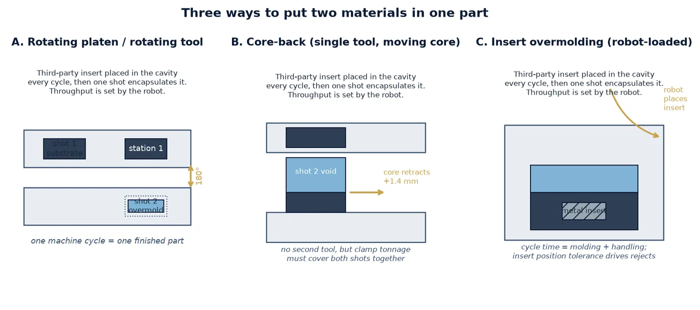
Four different processes get called two-shot, and they impose different constraints. Deciding which one you are buying is the first design decision, because it changes the tool, the machine and the wall thicknesses that are available to you.
| Process | How the second material arrives | Where it is the right answer | Constraint it imposes |
|---|---|---|---|
| Rotating platen or rotating tool | Both barrels on one machine; the half rotates between shots | Steady volume, one part every cycle, both materials in one tool | Mass and alignment of the rotating half; two barrels must match plasticising rate |
| Core-back | One cavity; the core retracts after shot 1 to open the second volume | Large parts, mid volume, a single machine | Clamp must carry both shots together; second-shot geometry is limited by core travel |
| Insert overmolding | A metal or plastic insert is placed in the cavity, then one shot encapsulates it | Threads, bushings, metal-to-plastic joints, low volume | Cycle time is set by handling; insert position tolerance becomes a reject source |
| Sequential or transfer overmolding | Part is moulded on one tool, moved to a second tool for the skin | Existing single-shot tools, small volumes, colour experiments | Second-shot shrinkage and flash differ from true two-shot; the first gate mark stays on the part |
The choice usually follows volume and how the part is assembled. Insert overmolding is the honest answer for a few thousand parts a year; a rotating tool only makes sense when the part will run for a long time.
Bonding is a mechanical problem before it is a chemical one
Two materials stay together for one of two reasons. Either the polymer chains at the interface entangle — which requires the substrate surface to still be molten, or at least above its glass transition, when the second shot arrives — or the geometry holds the skin in place. Chemical bonding is a bonus; the geometry is the guarantee.
This matters most with polypropylene. A TPE-S over PP will pass a peel test on the day of moulding and fail it after a week of handling if adhesion is all that holds it. Where the skin must survive assembly, ageing and a drop test, design an interlock.
| Substrate | Usual second material | Bonding reality | What to design in |
|---|---|---|---|
| PP, PP-TD | TPE-S / SEBS | Weak chemically; needs geometry | Through-holes Ø3–6 mm, dovetails, undercuts, textured pocket floor |
| PA6, PA66 (dry) | TPE-A, TPE-V | Moderate, but falls away if the substrate is wet | Dry the substrate before moulding; rough interface Ra 1.6–3.2 µm |
| ABS, PC-ABS | TPE-S, TPU | Good chemical bond | Keep the interface hot; avoid release agent contamination |
| PC | TPU | Moderate; sensitive to stress | Dry resin, gentle shear at the gate, no sharp interface corners |
| POM | Almost nothing bonds reliably | Mechanical only | Snap features and holes; do not specify an adhesive bond |
| PBT, PPS (glass filled) | TPE-V | Mostly mechanical; glass-rich skin | Anchor geometry; expect the interface to look dry |
Shut-offs: where two-shot parts leak
A shut-off is the vertical wall where the second cavity meets the first shot. It has to seal against moulding pressure while the skin is still flowing, and it has to survive being opened and closed for the life of the tool. The usual working figure is a vertical land of 3–8 mm height with 0.02 mm of closing clearance, hardened, and polished in the direction of opening.
Three failures repeat. The land is drafted, so the second shot pushes under it and flashes. The land is too short, so it wears a step and the flash grows gradually. Or the first shot’s vent is left open through the shut-off, so the elastomer follows the air out of the cavity. Venting belongs on the last-filled edge of the second shot, not on the seal.
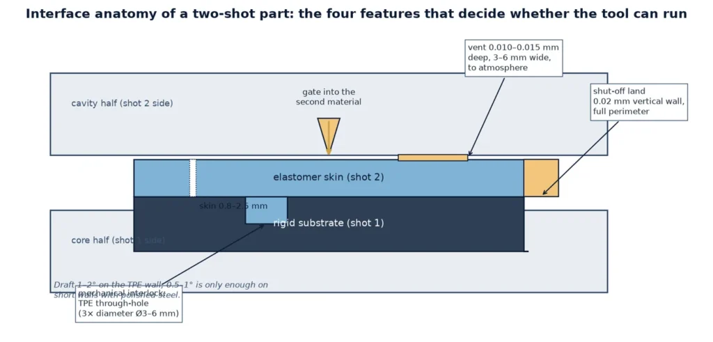
- Shut-off walls vertical, never drafted; draft belongs on the part, not on the seal.
- Land height 3–8 mm with hardened inserts where the tool runs above 500,000 cycles.
- Vent the second shot at the last-filled edge, 0.010–0.015 mm deep, 3–6 mm wide.
- Keep ejector marks off the shut-off band; a witness mark there becomes a leak path.
- Check the shut-off on the first-off part with a 10× loupe before approving cosmetics.
Wall thickness and shrinkage mismatch
The elastomer skin is normally designed between 0.8 mm and 2.5 mm. Below about 0.8 mm, a 40 Shore A material will not fill a long flow path before it freezes, and the moulder compensates with pressure until the shut-off flashes. Above roughly 3 mm, the skin sinks on the face opposite the substrate, the cycle lengthens, and the part gains weight that the application rarely needs.
The substrate has to take the second injection without deflecting: 1.2 mm is a practical floor for an unfilled resin, more where the second shot lands on a free span. Shrinkage then does the rest — PP at 1.2–1.8% against a TPE at 1.5–2.5% pulls the skin’s edge inward. A sharp lip tears; a radius of half the skin thickness, or a groove that traps the skin, does not.
| Feature | Working range | Why this range |
|---|---|---|
| Elastomer skin wall | 0.8–2.5 mm | Fills before freeze without sinking |
| Substrate wall under the skin | ≥1.2 mm unfilled | Resists second-shot injection pressure |
| Shut-off land height | 3–8 mm, vertical | Seals without a wear step |
| Interlock hole diameter | Ø3–6 mm | Holds the skin without stress cracking |
| Parting-line vent | 0.010–0.015 mm deep | Air escapes, flash stays closed |
| Elastomer draft | 1–2° | Releases without tearing the skin |
| Substrate surface roughness | Ra 1.6–3.2 µm | Mechanical key for the skin |
Gating the second shot
Gate the second shot into the elastomer, never through the substrate. A hot tip or a valve gate on the skin side gives a clean vestige that can be placed on a hidden face; a cold runner leaves a stub that has to be trimmed by hand, and every trim is a chance to lift the edge of the skin.
Flow length decides gate count. Soft TPE at 40 Shore A runs perhaps 80–100 times its wall thickness before pressure runs out; a 60 Shore D material reaches 150 or more. The second shot has less pressure available once the substrate is in the cavity, so a skin that needs four gates in a single-shot tool may need six.
- One gate per flow branch; balance by runner rather than by pressure.
- Keep gate vestige off sealing faces, sliding surfaces and any face the customer touches.
- Valve gates need a sequence: open after the substrate has cooled enough not to be washed away.
- Where the skin wraps an edge, gate away from the wrap so the flow front meets the edge last.
Machine sequence is part of the design
A drawing can be perfect and still fail because the machine cannot run the sequence. The second barrel usually has to plasticise in the shadow of the first shot’s cooling time, the second shot is normally 15–40% of the first by weight, and the rotating half adds mass that the platen has to carry every cycle.
| Machine check | Target when the tool is specified |
|---|---|
| Second shot weight against first | 15–40% of the substrate shot |
| Second barrel plasticising time | Fits inside the first shot’s cooling time |
| Rotating half mass | Inside the platen rating with margin left for the tool |
| Ejector position | Both halves, or a robot that can reach the rotating side |
| Clamp for core-back | Covers the projected area of both shots together |
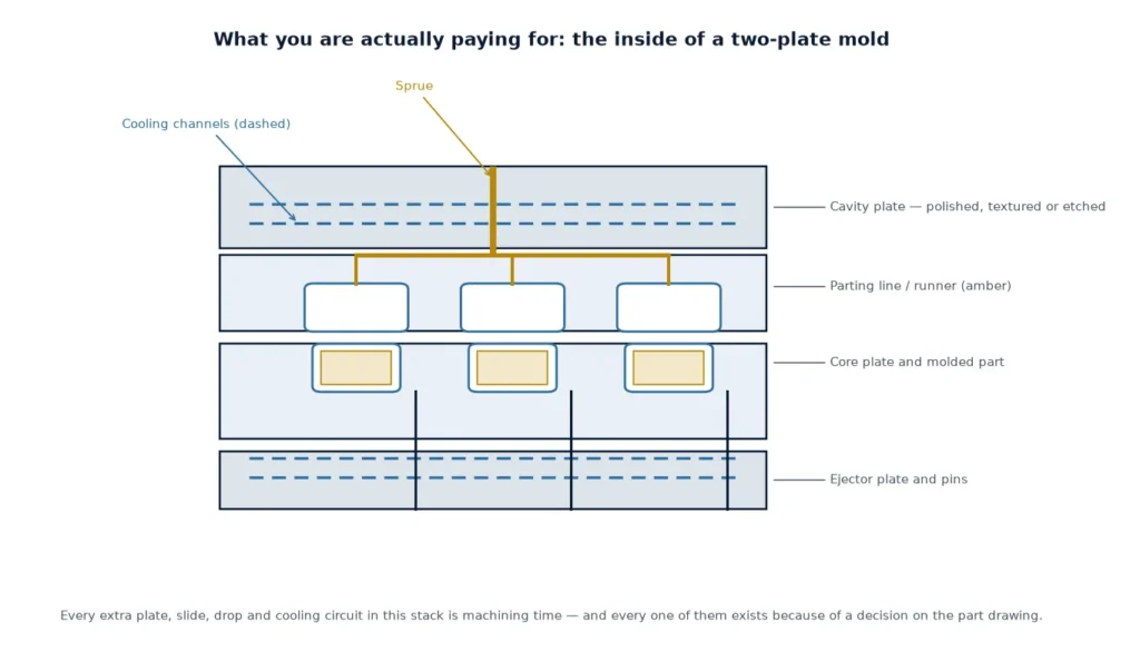
These choices also set the piece rate: a second barrel running below capacity, or a robot waiting on a slow ejection, shows up long after the tool is accepted. They are the same drivers described in what drives the cost of an injection mold.
What belongs on the drawing and in the RFQ
- The material pair with grades, not just families — “PP homopolymer + TPE-S 60A” beats “PP + rubber”.
- Which surfaces are cosmetic, and which may carry a gate vestige or an ejector mark.
- The bond requirement with a test method and a number: 90° peel in N/mm, or a pull-off value on a defined area.
- Interlock geometry dimensioned, including hole diameter, depth and edge distance.
- Shut-off surfaces identified on the 3D model so the toolmaker hardens the right walls.
- Ejection strategy: which half the part stays on, and where the ejector pins may land.
- Insert tolerances, if inserts are moulded in, including position and angularity.
- First-off documentation expected at T1 — dimensions, bond test and a photo record.
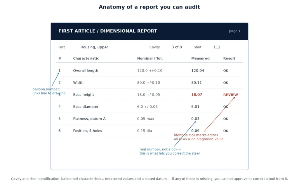
Inspection follows the same discipline as any other tool: a dimension report plus a functional test, agreed before the tool is cut. Reading a T1 trial report explains what FAI, a dimensional report and a PPAP submission each prove, and where a two-shot part needs a bond test on top of the dimensional data.
Where two-shot projects usually break at T1
Four failures account for most of the two-shot tools that come back for rework. The skin tears at ejection because the draft was taken from the substrate and not from the elastomer. A flash ring appears at the shut-off because the land is short or soft. The bond fails at the end of flow because the interface cooled before the second shot arrived. Or the part warps because the substrate is thin and the skin shrinks against it unevenly.
All four are diagnosable on the first-off part within an hour, and all four are cheaper to fix on the drawing than in hardened steel. If one is already running on a live tool, the symptom list in injection molding defects gives the measurement order before anything is ground.
Steel choice matters here too, though less than geometry. A shut-off that will run millions of cycles wants a pre-hardened, wear-resistant grade rather than a general-purpose one; the trade-offs are set out in mold steel selection: P20, 718H, S136 or NAK80. Two-shot tooling design itself sits inside the wider mold design and engineering process, where the second-half motion is modelled before the tool is released.
Frequently asked questions
Can any plastic be overmolded with TPE?
Almost any substrate can be overmolded if the geometry provides a mechanical hold. What changes is how much of the bond comes from chemistry: ABS, PC-ABS and PA bond well when dry, PP and POM rely on interlocks, and glass-filled resins generally need anchoring geometry because the surface is resin-poor.
How thick should the elastomer skin be?
Between 0.8 mm and 2.5 mm for most consumer and automotive parts. Thinner skins short-shot at the end of flow; thicker ones sink on the face opposite the substrate and add cycle time without adding function.
Do I need a rotating tool to make a two-shot part?
No. Core-back works on one tool for large parts, insert overmolding covers low volumes, and sequential overmolding can reuse two existing single-shot tools. Rotation is the highest-throughput option, not the only valid one.
Why does flash appear at the shut-off after a few months of running?
Because the shut-off land is wearing. A short land, a soft insert or a land that shares an edge with the parting line will develop a step, and the second shot then pushes into it. Hardened, vertical lands of 3–8 mm delay this for the life of the tool.
Can the second shot be gated on the visible face?
It can, but then the vestige has to be acceptable as a cosmetic feature. Most designs move the gate to a hidden face or an internal rib and accept a slightly longer flow path instead.
What test proves the bond?
A 90° peel test on a defined strip, reported in N/mm, plus a pull-off test on a moulded boss. Both need a number agreed before T1; “it feels attached” is not a specification.
Working on a two-shot or overmolded part?
Send the 3D model, the material pair and the cosmetic requirement. We will come back with the constraint list for your part and the tool concept that satisfies it.