Draft · geometry and release
Draft Angle in Injection Molding: How Much Each Feature Really Needs
One degree per side is the number everybody quotes, and on a tall textured wall it is not enough. Draft follows wall height, finish, resin and which side of the part the plastic grips.
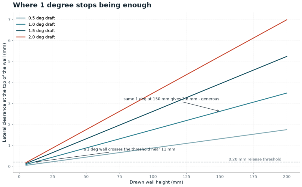
Ask three toolmakers how much draft a wall needs and you will hear one degree, one and a half degrees, and “whatever the last job had”. The one-degree answer is right often enough to be dangerous. On a 20 mm polished wall, one degree gives 0.35 mm of clearance, which is comfortable. On a 150 mm wall with a 60 µm texture, one degree gives the same 0.35 mm but the plastic now has to climb over every peak of that grain, and the part drags, whitens at the top edge and takes grain off the cavity. Draft is not a style preference. It is clearance, and clearance has to beat the friction of a shrinking part against a specific steel surface.
The short answer, feature by feature
These are the working numbers we design to. They are floors and habits, not a specification: a part with thick sections, deep ribs and a glass-filled resin wants the high end of every range in the table.
| Feature | Floor | Usual | What sets the number |
|---|---|---|---|
| Outer wall, polished, under 50 mm | 0.5° | 1° | polish direction, ejection area behind it |
| Outer wall, polished, 50–150 mm | 1° | 1.5–2° | wall height, shrinkage, draft lost to polish |
| Inner wall (core side), any height | 1° | 1.5–2° | plastic shrinks onto the core, not away from it |
| Rib, depth over 3x thickness | 0.5° per side | 1° per side | fill pressure, gas trap at the root |
| Boss outside diameter | 0.5° | 1° | height-to-diameter ratio, insert inside |
| Textured wall (SPI D2, ~60 µm) | +1° per 25 µm of texture | +1.5° | texture depth, pattern geometry |
| Steel shut-off / mating face | 3° | 5–7° | metal-to-metal closing, wear |
| Slide face or lifter | 2° | 3–5° | galling, side load, lubrication |
| Deep pocket over 4x width | 1.5° | 2–3° | core stiffness, air trap at the bottom |
Clearance is height times the tangent, and nothing else
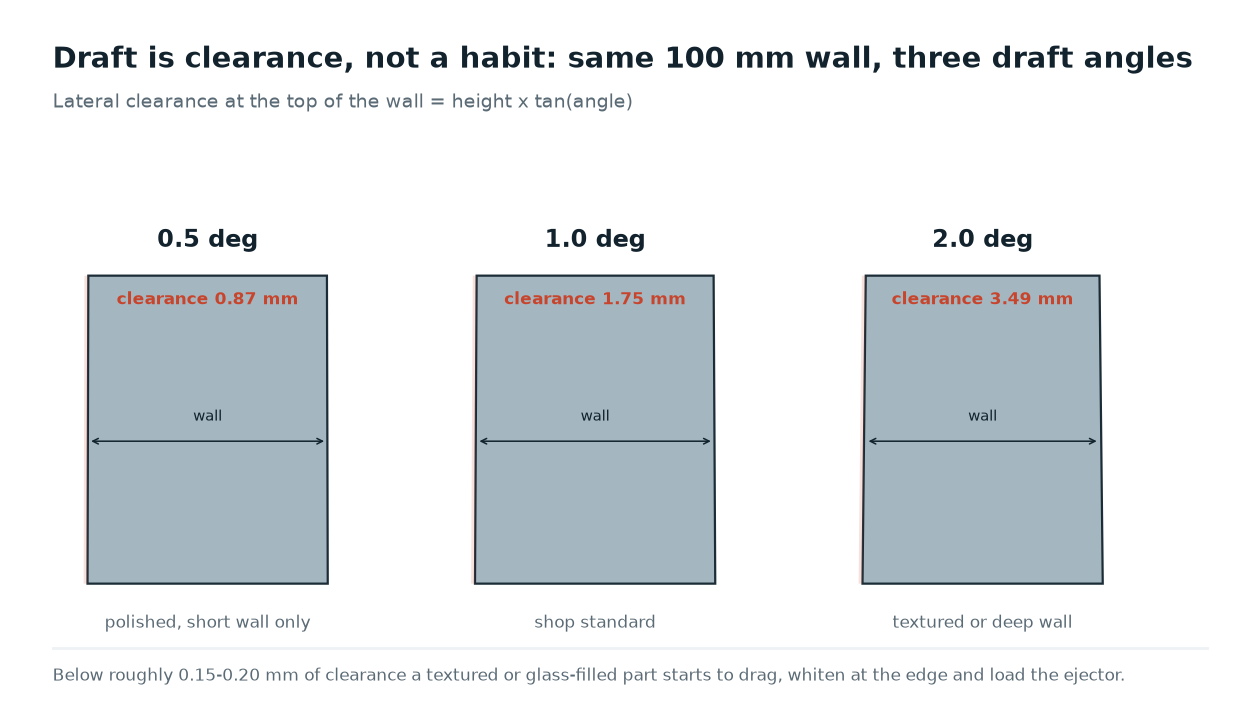
The lateral gap at the top of a drawn wall is h × tan(θ). That is the whole formula, and it explains why the same angle works on one part and fails on the next. One degree over 20 mm is 0.35 mm. One degree over 150 mm is 2.6 mm. Half a degree over 100 mm is 0.87 mm, which sounds fine until the wall is textured and the effective gap at the grain peaks is half that. As a working threshold: below roughly 0.15–0.20 mm of real clearance, a textured or glass-filled part starts to drag, the ejector load climbs, and the top edge of the part shows white stress marks that no amount of packing pressure will remove.
The core side is not the cavity side
Plastic shrinks onto whatever steel it is wrapped around, so a wall drawn off the core faces more friction than the same wall drawn out of the cavity. On a box, the outside of the box can run at 1° while the inside needs 1.5–2°, and the difference is not laziness: it is the shrink direction. If you are short of room and can only add draft in one place, add it to the core side first, then to the deep pockets, then to the textured faces. The outer wall is the last place you need to win the argument.
Surface finish eats draft before anything else does
A polished A2 cavity can run 0.5–1° on a shallow wall. Put a 60 µm texture on the same wall and the plastic has to climb over the grain: the working rule is an extra degree per 25 µm of texture depth, on top of the geometric minimum. That is why a cosmetic part with a leather grain ends up at 4–5° on the sidewall and the drawing suddenly looks nothing like the previous revision. The finish specification and the draft specification have to be written at the same time; our guide to SPI mold finish standards and texture covers how the grades map to depth, and why a VDI number does not convert cleanly into an SPI one.
Where the nominal dimension goes
Adding draft changes dimensions, and somebody has to decide which face keeps the nominal value. Three habits work. Hold nominal at the parting line, where the steel is fixed and the shut-off is defined. Hold nominal on the functional face — the sealing land, the mating plane, the datum face — and take the draft out of the non-functional side. Never split the difference across both faces, because then nobody can inspect the part and the tolerance stack has two moving references. On the print, show the draft as an angle on the drawing views, not just a note, and give the model with draft already built in so the CAM programmer is not inventing it. Where draft interacts with the dimensional window, the same numbers that govern shrinkage and dimensional tolerance apply.
Resin changes the bias
The angle that releases ABS will drag on unmodified PA66 with 30% glass, and a soft TPE will come off a core that a rigid PC part would grip. The reasons are shrink rate, stiffness and how the material behaves against polished steel.
| Resin | Typical shrink | Release behaviour | Draft bias |
|---|---|---|---|
| ABS | 0.4–0.7% | moderate grip, forgiving | table values |
| PP | 1.2–2.0% | soft, high shrink, sticks to gloss steel | +0.5° on core side |
| PA66 + 30% GF | 0.3–0.7%, strongly anisotropic | stiff and abrasive, whitens easily | +0.5°, plus wear allowance |
| PC | 0.5–0.7% | high viscosity, needs fast fill | table values, watch fill pressure |
| POM | 1.8–2.5% | low friction but high shrink | +0.5° on long walls |
| Rigid PVC | 0.4–0.6% | corrosive, cavity must be plated | table values |
| TPE / TPV | 1.0–2.5% | flexes off the core | 0.5° can be enough on shallow walls |
Six places draft quietly disappears
- Polishing removes steel unevenly, so a 1° wall can come back from the bench at 0.7° in the middle and 1.3° at the ends.
- A textured or bead-blasted patch has no draft credit at all until the etcher measures depth.
- Ribs and bosses are drafted on the model but the electrode for the EDM leaves a radius at the root that eats the first half degree.
- A slide face that closes on an angled surface loses draft where it shuts off, and gains an unwanted step in the part.
- Insert pockets and shut-offs around metal inserts are usually the tightest walls on the tool, and they are drawn off the core.
- Two-shot and overmolded substrates get drafted for the first shot, then the second shot closes on the same wall and the draft now works against the overmold.
How short draft shows up in the trial
You rarely see “insufficient draft” on a defect list; you see its symptoms. Drag marks running along the draw direction, polished steel going dull in a band, whitening at the top edge of a wall, a hollow sound as the part releases, ejector pins that leave a raised witness mark because the ejection force had to be pushed up, or a part that comes off with a squeal and a torn corner. In a bad case the grain lifts off the cavity in patches and the tool goes back to the bench. If ejection force is already the limiting factor, the fixes and their trade-offs are set out in our guide to ejection system design.
What to put on the drawing and the RFQ
- Draft per face, as an angle, on both the cavity and core sides — not one global note.
- The face that holds nominal, named explicitly (parting line, sealing land, datum).
- Texture grade and measured depth, so the draft adder can be calculated instead of guessed.
- Minimum clearance at the top of every drawn wall, if the buyer has a preference; it removes the argument about angle versus height.
- Any wall where draft is capped by function, flagged early — a zero-draft sealing land is a design decision, not a toolmaking error, and it changes how the tool is built.
- Whether the model is supplied with draft already applied, and to which tolerance.
Most draft problems are cheap to fix on a print and expensive to fix on steel. The full pre-cut review list is in our DFM checklist before cutting steel; if a wall on your part is on the edge, send us the model and the resin and we will mark the faces where the number has to change.
Frequently asked questions
What is the minimum draft angle for injection molding?
Half a degree per side is the absolute floor and only on short polished walls. One degree per side is the working minimum for a polished wall, one and a half to two degrees on the core side where the plastic shrinks onto the steel, and an extra degree per 25 µm of texture depth.
Is 1 degree of draft always enough?
No. One degree gives 0.35 mm of clearance over a 20 mm wall and 1.75 mm over a 100 mm wall, so it is generous on short walls and marginal on tall ones once texture, glass-filled resin or a deep core is involved. Check the clearance at the top of the wall, not the angle alone.
Does draft add to the part size or take it away?
It depends which face holds nominal. If nominal is at the parting line, the part grows toward the far end of the draw. If nominal is on a functional face, the draft is taken out of the opposite side. Decide this before the steel is cut, because it moves the whole tolerance stack.
How much extra draft does a texture need?
About one degree per 25 µm of texture depth on top of the geometric minimum, so a 60 µm grain typically wants two to three degrees of extra draft on the drawn wall. Deep grain, tight ribs and glass-filled resin are additive.
Can a soft TPE or TPU run with less draft?
Yes. A soft grade flexes off the core, so 0.5° is often enough on a shallow wall. The same wall in a rigid, glass-filled engineering resin needs two degrees or more. Do not transfer a TPE draft number to a rigid part.
Where should draft be shown on a mold drawing?
As an angle on each drawn face in the section views, plus a note naming the face that holds nominal. A single global note such as “all walls 1° draft” is not enough, because it cannot express the core side, the texture adder or the shut-offs.
Send the model before the steel is cut
We review draft, wall thickness, texture and shut-offs against the resin you intend to run, and mark the faces where the number has to change — before electrodes are made.